- Research
- Open access
- Published:
Design of double codebook based on 3D dual-polarized channel for multiuser MIMO system
EURASIP Journal on Advances in Signal Processing volume 2014, Article number: 111 (2014)
Abstract
This paper proposes a precoding method based on double codebook for multiuser three-dimensional multiple-input multiple-output (3D MIMO) system deployed with dual-polarized antenna array. Considering the block diagonal feature of the transmit correlation matrix of 3D dual-polarized channel, we adopt the double codebook structure, where the precoding matrix is composed of an inner long-term matrix and an outer short-term matrix. Then, we introduce a set of 3D beams which possess good discrimination in horizontal and vertical domains to be the basic beam set and adopt a topology describing the 3D beam set to illustrate the angle information in an intuitive way. For the purpose of multiuser transmission, we also propose a corresponding limited channel information feedback scheme and a user scheduling criteria based on this double codebook structure. Simulation results demonstrate that the precoding method based on double codebook for the dual-polarized 3D MIMO system effectively improves system throughput compared with 2D transmission scheme.
1 Introduction
By applying multiple antennas at the transmitter and receiver, multiple-input multiple-output (MIMO) techniques can exploit spatial degrees of freedom and improve the spectral efficiency[1]. Although initial work on multiple-antenna design was primarily motivated by the single-user paradigm, more recent attention has been on the theory and practice of multiuser (MU) multiple-antenna communications[2–5]. A transmission strategy using dirty paper coding (DPC) was proposed in[6, 7] and shown to achieve the system capacity. However, it is extremely computationally intensive, especially in the multiuser context. This makes it less attractive in practical systems, and low complexity sum-optimal schemes are desirable. Therefore, many linear precoding methods appear, such as zero-forcing precoding and block diagonalized precoding. In 3GPP Release 10, a double codebook-based precoding method was proposed[8]. It adopts discrete Fourier transform (DFT) beams as the basic beam set, which behaves well under uniform linear array (ULA) antenna array deployment. The scheme takes advantage of the block diagonal feature of the channel’s transmit correlation matrix and selects beams according to both long-term and short-term channel state information (CSI). However, most traditional MU-MIMO systems are designed with respect to a two-dimensional (2D) world. By choosing beams with different azimuths, the base station (BS) can simultaneously provide service to several users located in different horizontal directions. All the beams are with the same downtilt; therefore, users in the same horizontal direction referring to BS cannot be scheduled at the same time, as shown in Figure1a. If several users are distributed in different floors of a tall building, only one of them will be served.

Examples of (a) a 2D MU-MIMO system and (b) a 3D MU-MIMO system.
With the rapid development of high-rise buildings in modern cities, there has been a growing range of floors users may stay in. This challenges the traditional channel model and transmission techniques. In recent years, three-dimensional (3D) MIMO techniques, which fully exploit the degrees of freedom in 3D space, have attracted more and more attention[9–20]. Compared with 2D MU-MIMO, the 3D MU-MIMO system is able to simultaneously serve several users who have the same azimuth but are located at different heights and therefore improves transmission efficiency greatly, as shown in Figure1b. To realize 3D MIMO, changes are required for both channel model and transmission scheme. A new 3D channel model has been set up by 3GPP[9], where the concept of downtilt or elevation angle is added as an important channel parameter, BS is deployed with uniform planar antenna array (UPA), and users are distributed in every floor instead of just moving on the ground. Based on the 3D channel model, some 3D beamforming methods that adjust the beam downtilt adaptively according to elevation sectorization or per-user elevation were proposed[10–15]. A 3D beamforming method for hexagonal multicell network was proposed in[10], which implements an implicit coordination scheme to control multicell interference by vertically and horizontally assigning different resources to adjacent sectors. The methods in[11] and[12] are based on cellular segmentation, the whole cell is split into several concentric annular zones, and each of them is allocated with a fixed beam downtilt. Two user-specific elevation beamforming methods based on adaptive codebooks derived from channel correlation matrix are proposed in[13, 14]. However, they are designed for single-user transmission systems. Another per-user adaptive beamforming method raised in[15] calculates the downtilt by comprehensive channel estimation and then applies the estimated downtilt to traditional 2D LTE precoding. Existing techniques generally consider horizontal domain and vertical domain independently; therefore, relevant beamforming is implemented in horizontal and vertical domains separately.
In this paper, we investigate the 3D MU-MIMO downlink transmission system and propose a joint-domain precoding method which considers both horizontal and vertical domains simultaneously. This method is based on double codebook and designed for MU-MIMO systems under the deployment of dual-polarized UPA antenna array at BS. The double codebook structure is adopted here under the consideration of the block diagonal feature for the channel’s transmit correlation matrix. The precoding matrix is composed of two components: inner precoding matrix and outer precoding matrix. The inner precoding matrix roughly orients the direction of the channel’s main lobe and is decided by long-term CSI, i.e., transmit correlation matrix. The outer precoding matrix is used for precise positioning and is decided by instantaneous CSI. A set of 3D beams which has good discrimination in horizontal and vertical domains is selected to be the basic beam set, and a UPA topology is introduced to demonstrate the angle relations among these 3D beams. This paper also proposed a best companion cluster (BCC) limited feedback scheme and a user pairing criteria in multiuser transmission mode. Users calculate the optimal inner precoding matrix index (PMI1), the optimal outer precoding matrix index (PMI2), the optimal pairing cluster index (CI), and channel quality indicator (CQI) according to downlink channel estimation results and feed these values back to the BS, and then the BS uses feedback values to implement user pairing and scheduling. Moreover, a fast codebook searching method is presented for the purpose of saving calculation time when the codebook size is huge. Simulation results show that the proposed 3D transmission method can effectively improve system throughput compared to the 2D transmission method.
The rest of this paper is organized as follows. Section 2 presents the antenna array model and 3D MU-MIMO downlink transmission model. Basic beam set and precoding method based on double codebook are described in Section 3. In Section 4, the CSI feedback scheme, user scheduling criteria, and fast codebook searching method are illustrated. Simulation results and analysis are given in Section 5. Finally, Section 6 concludes the paper.
Notation: In this paper, matrices and vectors are denoted by uppercase and lowercase boldface letters, respectively. We use I to denote the identity matrix and 0 to denote the all-zero matrix. The superscripts (·)H, (·)T, and (·)∗ represent the conjugate-transpose, transpose, and conjugate operations, respectively. Symbol represents the expectation with respect to all random variables within the brackets. A ⊗ B is the Kronecker product of matrices A and B. We use |·| and ∥·∥ to denote taking absolute value and modulus operations, respectively.
2 System model
In this section, we provide detailed introduction to the system model, focusing on the antenna array topology and the downlink transmission scheme. We consider the single-cell 3D MU-MIMO downlink transmission system. The BS is located at the cell center. A total number of K users are distributed randomly in the cell. According to the typical scenario in the 3GPP 3D channel model, some of the users are located in high rises, while others are moving on the ground at a low speed.
2.1 Antenna array model
It has been proved that large-scale multiple antenna array deployment can significantly improve spatial resolution and diminish inter-user interference (IUI) due to its extremely narrow transmit beams[21], along with the challenges of terminal size and price. Dual-polarized antennas become widely employed for saving half of the space that the antenna array covers while maintaining the same data transmission rate.
Based on the above considerations, in this paper, a dual-polarized UPA antenna array is adopted at BS as the 3GPP 3D channel model recommends, and each pair of dual-polarized antennas is positioned equidistantly on a wall, as shown in Figure2. In this UPA array, there are and antenna pairs in each row and column, and the distances between any two adjacent rows and columns are and, respectively. Thus, the total number of dual polarized antenna pairs is, and the total number of transmit antenna elements is 2 × N tx . Now, for simplicity, we consider a single polarized direction and suppose there are only vertical-polarized antenna elements, as shown in Figure3, where γ t and θ t are the beam downtilt and azimuth, respectively, and each antenna port serves one antenna element[19]. The antenna array response can be expressed in the following way
where,, and λ is the carrier wavelength. The derivation of (1) can be found in the Appendix. At the user side, N r x pairs of dual-polarized antennas are assigned into the ULA array. A numbering method for UPA is also introduced in Figure3 for convenience.

Dual-polarized UPA topology. Each cross represents a pair of dual-polarized antennas. The blue lines are vertical-polarized antenna elements, and the red lines are horizontal-polarized ones.

Beam downtilt γ t , beam azimuth θ t , and an S -shaped sorting method.
2.2 Downlink transmission
In this paper, we consider a two-user spatial division multiple access (SDMA) system. In the 3D MU-MIMO system, users firstly estimate CSI using downlink pilot signals and feed the estimated CSI back to BS, and then BS uses the information to conduct downlink multiuser transmission. The estimated CSI includes information about the selected precoding matrix, i.e., PMI1 and PMI2, and user pairing and scheduling accordance, i.e., CQI and CI. Figure4 shows the block diagram of the downlink transmission system.

Downlink transmission model.
Assume that the two scheduled users are u and s. The received signal at user u can be written as
where and are signals for users u and s with power constraint, N l is the transmission rank, P is the total transmit power, is zero-mean complex additive Gaussian noise satisfying, is the channel matrix of user u, and and are the precoding matrices for users u and s, respectively. Minimum mean square error (MMSE) receivers are applied at the user side[22], and the signal-to-interference-plus-noise ratio (SINR) matrix of user u can be expressed as
where. Based on (2) and (3), the system throughput can be calculated as follows:
The target of the proposed scheme is to maximize the system throughput with respect to W u and W s . In the rest of this paper, we will consider the rank 1 transmission mode, i.e., N l = 1. In this case, vectors x u and x s are reduced to scalars x u and x s .
3 Precoding based on double codebook
In this section, we discuss the design of the precoding matrix. As is mentioned above, the double codebook structure is adopted in our precoding matrix design, where the precoding matrix W is the product of two matrices W = W1W2, and they are selected from a long-term codebook and a short-term codebook, respectively. Inner precoding matrix W1 roughly orients the direction of the channel main lobe and is decided by long-term CSI, i.e., channel’s transmit correlation matrix. In the case of flat fading channel whose statistical information is regarded to be unchanged for a long period, W1 remains constant during this period. Outer precoding matrix W2 is used for precise positioning and is decided by instantaneous CSI. Since such information changes over time, W2 should be synchronously updated with the instantaneous channel. Due to the block diagonal feature of the transmit correlation matrix of the 3D dual-polarized channel, the length of each codeword is only half of the total number of transmit antennas, i.e., N tx , which contributes to dimensionality reduction. Comprehensive utilization of both long-term and short-term CSI also results in feedback period extension. To discuss the design of inner precoding matrix W1, we first introduce the selection of basic beam set and then explain the design of inner precoding and outer precoding matrix in detail.
3.1 Basic beam set
Theoretical research has shown that the deployment of UPA topology used in BS antenna array can greatly exploit the vertical domain and adjust the beam direction in 3D space feasibly[20]. The orientation of a beam is determined by downtilt γ t and azimuth θ t , as shown in Figure3. We can split the whole 3D space using γ t and θ t and select N v downtilt values from [-π/2,π/2] and N h azimuth values from [0,2π]. If we combine these values together, the complete set of basic beams will be defined, which covers N v × N h directions totally. These basic beams can be regarded as a set of basic vectors in 3D space, and any spatial vector can be represented using this set. Let c i represent the i th beam. The basic beam set can be displayed in the form of UPA topology shown in Figure3, where the downtilts of the beams in a row are the same, so do the azimuths of the beams in a column, as shown in Figure5.

Basic beam set displayed in UPA topology.
In practical situations, users are located in a small range in the vertical domain. Downtilt values of the basic beams are not uniformly distributed in [-π/2,π/2] but centralized in a small range. In this case, as presented in Figure5, the right semi-circle is non-uniformly segmented. However, the UPA topology for the basic beam set is still available. Existing 3D beamforming techniques satisfying this UPA topology includes the Kronecker product-based codebook (KPC) precoding scheme[23]. KPC is derived from the traditional DFT codebook by making the Kronecker product of horizontal DFT codewords and vertical DFT codewords as follows:
where β is a parameter related to the abovementioned regional centralization of user distribution in the vertical domain. Obviously, KPC codewords are designed according to the transmit antenna array response (1); therefore, they can match the 3D spatial channel model well. Figure6 gives an example of the projection of KPC beams onto the horizontal plane when. Beams c1 and c9, c225 and c233 lie in the same row of the UPA array, respectively; meanwhile, c1 and c225, c9 and c233 are in the same column. Energy distribution of these beams illustrates that the downtilts of c1 and c9 are the same, as well as the azimuths of c1 and c225, demonstrating that the KPC beams satisfy the previous angle requirement for the basic beam set.

Examples of KPC beams: c 1 , c 9 , c 225 , and c 233 . The order of the four subfigures reflects the row and column relationship among these four KPC beams.
According to the 3GPP 3D channel model[9], in (5) is no longer able to cover the high-rise situation. Knowing that the value set of parameter m corresponds to a N v -size subset taken out from a β N v -size downtilt value set, it can be changed according to the practical situation. For example, for the case in Figure7, the value set of m can be selected as {-3,-2,⋯,6}, covering all the potential situation including both the high rise and the ground.

Downtilt value set for high-rise scenario.
3.2 Precoding matrix design
Inner precoding roughly orients the channel and captures the channel’s main lobe by choosing a few basic beams that are adjacent to each other. Under the deployment of dual-polarized antenna array, transmit correlation matrix R of the channel holds the following block diagonal feature:
where A and B are the transmit correlation submatrices of two polarization directions and are approximately equal. According to this long-term character, the k th inner precoding matrix in the long-term codebook is defined as
where X k is a N tx × N b matrix representing the k th subset of the basic beam set which contains N b basic beams, N b = N bv N bh , N bv and N bh are the row and column number of each basic beam subset. Figure8 gives an example of X k and illustrates its position in the complete basic beam set as the dotted line surrounds., i = 1,⋯,N h N v , and the relationship between i and k is decided by the definition of basic beam subset.

Basic beams in X k are included in the dotted line, equivalent to a beam subset.
If the complete set is uniformly segmented and non-overlapping exists among subsets, the numerical relation between the complete set and the beam subsets satisfies
where m,n are integers. Referring to the Release 10 scheme[8], to avoid border vagueness, we can consider the method of overlapping among subsets, and the overlapping ratio between adjacent subsets is 1/2. In such case, the selected subsets have higher possibility to cover the channel main lobe, but the amount of subsets doubles afterwards. Here we use three overlapping definitions, that is, overlapping in only the horizontal domain, in only the vertical domain, and in both domains. Take N v = 4,N h = 32,N bv = 2,N bh = 4 case as an example, and four different segment methods are shown in Figure9.

Four different methods to segment the complete set of basic beams. (a) Uniform and non-overlapping, (b) uniform and overlapping only in the horizontal domain, (c) uniform and overlapping only in the vertical domain, and (d) uniform and overlapping in both domains.
Outer precoding is used for beam matching. The beams best matching the current instantaneous channel will be picked out from the previous selected subset. Considering rank 1 transmission, only one beam will be selected, and therefore, the l th outer precoding matrix in the short-term codebook is expressed as follows:
where
i = 1,⋯,N b and α is a phase parameter from the QPSK signal set {1,j,-1,-j}. There are altogether 4N b alternatives for W2.
4 Multiuser transmission based on double codebook precoding scheme
Double codebook structure can greatly reduce the amount of CSI feedback, shorten the feedback period, and improve transmission efficiency of the FDD system. In this paper, we choose BCC as the corresponding limited feedback scheme. There are four values to be calculated, that is, inner precoding matrix index PMI1 which is related to parameter k, outer precoding matrix index PMI2 which is related to parameter l, the cluster indices CIs that a user himself and his best companion are included in, and the channel quality indicator CQI reflecting channel condition when interference exists. According to Figure4, users estimate CSI and use these estimation results to match beams step by step until PMI1 and PMI2 are settled. CI and CQI will also be calculated and sent back to the BS along with PMI1 and PMI2. In downlink, the BS uses these feedback values to conduct user scheduling and beam selecting, then implements multiuser transmission. Since a large size basic beam set is usually adopted, in this section, we propose a fast codebook searching method for the purpose of saving PMI1 calculation time.
4.1 Calculating the feedback values
(1) PMI1 calculation: When selecting PMI1, statistic channel information is used and assumed to be constant during T sampling intervals. For user u, we firstly calculate its transmit correlation matrix
Under the deployment of dual-polarized antennas, R u has block diagonal structure[24]
where, and. Therefore, we use the following equivalent transmit correlation matrix to represent the transmit correlation matrix
Implement singular value decomposition (SVD) to and choose its principle eigenvector v1 as the long-term channel main lobe direction. Then, calculate the distances between v1 and all the basic beams, and select the nearest one c i and the farthest one c j ,
If non-overlapping method is used, we can calculate PMI1 directly from c i . When utilizing overlapping methods, there are more than one subset that contains c i , and further processing is required to choose the best subset. In this case, the second primary eigenvector v2 of can be taken out to match with the beams included in the several selected subsets, until the final PMI1 is selected.
(2) PMI2 calculation: PMI2 is decided according to the instantaneous channel information H u . Outer precoding W2 should maximize the power of the received signal, and therefore, PMI2 for user u is determined as follows:
(3) CI calculation: A simple way of defining CI proposed in Release 10 feedback scheme[24] is to directly regard the subset index PMI1 u wherein the fittest beam c i is referred to as the belonged cluster index CIi u , and regard the subset index PMI1 s wherein the farthest beam c j is referred to as the optimal paired companion cluster index CIj u , that is, CIi u = PMI1 u , CIj u = PMI1 s . However, in order to reduce the size of the short-term codebook, only a few beams are included in X k , resulting in complex subset segmentation and large amount of subsets. If we apply the above method and only use PMI1 to implement user scheduling and pairing, successful paired rate will be low unless the number of users is large. In this paper, we revise the definition of CI, cluster several adjacent PMI1 into a CI, and increase the paired rate by means of decreasing the number of companion clusters. PMI1 array in the form of UPA is shown in Figure9. Considering the concentrated user distribution in the vertical domain and the uneven segmentation that KPC acts on 3D space[23], CI calculation is illustrated in Figure10, where the gray blocks represent PMI1 values. While uniformly clustered in the horizontal direction, PMI1 values are vertically clustered according to the sparsity of beam downtilts in the ratio of 1:3. This method will maximize user paired rate and guarantee IUI as slight as possible.

New principle of calculating CI. Uniformly clustering in horizontal direction and vertically clustered in the ratio of 1:3.
(4) CQI calculation: CQI of user u is conservatively calculated as follows:
4.2 User scheduling
Having received all the information that users feed back, BS uses these feedback values to implement user pairing and scheduling as follows:
-
Step 1 Primary user selection. BS finds out the maximum CQI and chooses the corresponding user for primary consideration.
-
Step 2 Paired cluster selection. According to the long-term information (CIi u ,CIj u ) of user u, BS finds out its paired cluster whose CI values are exactly (CIj u ,CIi u ).
-
Step 3 User scheduling. Choose user s whose CQI is the maximum one of successful paired cluster as the best pairing user and simultaneously scheduled with primary user u.
4.3 Fast codebook searching method
The deployment of a large-scale antenna array can exploit enough spatial degrees of freedom; nevertheless, it results in large-scale codebook, i.e., with 102 or more codewords. Generally, when using CSI to do beam matching, we calculate the distances individually and take the best one. It is a traversal method (TM) and is highly time-consuming when conducted for searching a 3D codebook. Here, we propose a new fast codebook searching method (FCSM), utilizing the UPA topology of the complete basic beam set shown in Figure5. Generally, the value of N v or N h is a power of 2, so here we consider a quartering method.
-
Quartering step 1 We divide the complete beam set arranged in UPA form into four subsets A1,A2,A3, and A4, signed as the first-order subset. Figure11 shows quartering step 1, where small circles are codewords, and the four red circles at 1/4 and 3/4 positions of the top and bottom rows represent reference codewords,,, and. When calculating PMI1, firstly compare CSI with these four codewords and pick out the optimum one, for example,, then search subset A1 and no longer consider A2,A3, and A4.
Figure 11 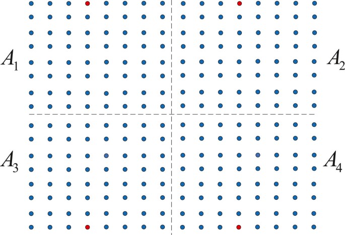
Quartering step 1.
-
Quartering step 2 If the size of subset A1 is still too huge, we further conduct quartering and get the second-order subsets B1,B2,B3, and B4. Now we use codewords in four vertices instead of the 1/4 and 3/4 positions of the top and bottom rows as new reference codewords, as shown in Figure12. Continue to compare CSI with the new reference codewords and select the best second-order subset, such as B2, without further consideration about the remaining three subsets.
Figure 12 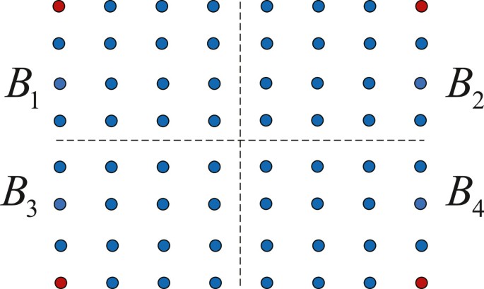
Quartering step 2.
-
Quartering step 3 Repeat quartering step 2 until there is no need for a higher-order subset. Then, we simply compare the CSI with beams in the smallest subset individually and find the best one.
Notation: Since the first and the last columns of the complete beam set are actually adjacent with each other, we select the center, not the vertex of each first-order subset, to be the reference codewords in quartering step 1. However, for each second-order subset, its two side-columns lose adjacency, becoming suitable for reference in quartering step 2.
The idea of quartering is applicable for not only codebook searching but also other utilities. If only the samples to be searched can be arranged uniformly in UPA form, quartering method will be applicable.


5 Numerical results
The performance of the proposed precoding method based on double codebook for the 3D dual-polarized MU-MIMO system is investigated through simulation. Numerical results about the design of precoding matrix including four different methods to segment the complete set of basic beams and the multiuser transmission scheme are presented in this section. The performance of 2D precoding under the same deployment is also shown for comparison. Simulation parameters are listed in Table1.
Consider a 120° sector of a 500-m-radius cell. Users are uniformly distributed in the sector, with a minimum 2D distance of 10 m from BS. To better fit modern urban condition, we assume that all users stay in an eight-floor building whose storey height is 3 m, and the bottom floor is equivalent to the ground; therefore, the effect of user height is significant. Energy loss caused by signals traveling through walls from outdoor to indoor and other similar factors are ignored here. WINNER 3D channel model is adopted, and C2 urban macro in NLOS condition is selected[25]. When implementing 2D scheme, the downtilt of each transmit beam is fixed to 12°, and the value set of CI is {1,2,…,8}.
Figure13 compares the throughput of the 3D multiuser transmission scheme based on dual-polarized channel and that of the 2D scheme when the size of BS antenna array is, i.e., the total number of transmit antenna elements is 2 × (8 × 8). From the figure, it can be seen that the throughput of the MU-MIMO system using the proposed precoding method based on 3D beams is higher than the traditional precoding method which uses 2D beams, since 3D beams perform better than 2D beams in describing and matching 3D channel. Precoding based on 3D beams can adaptively adjust the beam downtilt according to the vertical channel information, while precoding using 2D beams simply unifies all the beam downtilt and only makes use of the horizontal channel information. Moreover, if we increase the number of users, successful paired rate grows, and system throughput increases. Performance comparison of the four different methods to segment the basic beam set is also shown in Figure13. When there are only a few users, the performance of non-overlapping method is not better than that of overlapping method. While with the growth of user number and successful paired rate, the advantage of overlapping method becomes gradually significant. Successful paired rate of these above methods is compared in Table2. It is obvious that the overlapping method in both domains maximizes system throughput; thus, it is more suitable for our multiuser feedback scheme in single sector scenario. The achieved throughput when using the vertically overlapping method is higher than when using the horizontally overlapping method. If more comprehensive division in the vertical domain is employed for calculating feedback value CI, the advantage of vertically overlapping method will be further exploited.

Throughput comparison when users are distributed in a 120° sector.
Since beams in each row of KPC cover the whole 360° plane, performance of the proposed scheme is also tested in the whole cell scenario. The previous directive antennas are replaced by omnidirectional antennas, i.e., A H (ϕ) = 0, and users are distributed uniformly in the cell. Figure14 and Table3 give the simulation results. In this scenario, the overlapping method in both domains loses the excellence achieved in the 120° sector scenario, although surpasses non-overlapping method when user number is large, and it does not perform better than the two single-domain overlapping methods. In conclusion, overlapping method in both domains is recommended in the 120° sector scenario and vertically overlapping method is suggested in the whole cell scenario.

Throughput comparison when users are distributed in a whole cell.
To investigate the performance of fast codebook searching method, the principle eigenvector v1 of the transmit correlation matrix of the channel between user 1 and BS is taken out and matched with beams using the proposed method and traditional traversal method, respectively. A total of four KPC codebooks with different sizes are tested here, and the numerical results are given in Table4. In order to diminish iterations in fast searching method and maximize its calculating efficiency, the quartering is stopped when the third-order subset is segmented. According to the data in Table4, if a small-size codebook is used, for example, N v × N h = 16 × 32, these two methods will cost the same amount of time, and thus fast searching method cannot save time. With the enlargement of codebook size, time consumption of traversal searching grows linearly, while the increased time for fast searching is small, especially in N v × N h = 64 × 64 condition, and fast searching costs only 1/6 of the traversal searching time. Searching results of the two methods show that the correct ratio of the proposed fast searching is high. Therefore, our proposed fast searching codebook method can effectively reduce the calculation time of the feedback value PMI1 and at the same time guarantee high accuracy when the size of codebook is large.
6 Conclusion
In this paper, we considered 3D dual-polarized MU-MIMO system and proposed a precoding method based on double codebook. Considering the block diagonal feature of the transmit correlation matrix of 3D dual-polarized channel, we adopted the double codebook structure for precoding design, conducted beam matching, and calculated feedback values according to both long-term and short-term CSI. We also proposed a multiuser transmission scheme based on BCC limited feedback scheme and designed a fast codebook searching method for large-scale codebooks. Simulation results showed that when compared with 2D precoding method, the proposed precoding method based on 3D beams can effectively improve system throughput, and the fast codebook searching method can reduce the calculation time of the feedback value and at the same time guarantee high accuracy.
Appendix
Derivation of Equation 1
In this appendix, we give the specific derivation process of the UPA antenna array response in (1). According to Figures2 and3, when a signal gets through the UPA array, we can analyze its phase shift in horizontal and vertical domains, respectively. If we take out all the antenna elements in the n th column, then a uniform linear array (ULA) is formed, as shown in Figure15. The phase shift between the m th antenna element and its same-column adjacent element is[26, 27]

A column taken out from UPA antenna array. represents the equivalent delay distance between two vertically adjacent antenna elements.
where c represents the propagation rate of the carrier satisfying c = λ f. From Figure15, we can easily find that
and therefore, φ(v) can be expressed as
Similarly, the phase shift between UPA element (m,n) and its same-row adjacent element is
When compared with the first antenna array element, the total phase shift of (m,n) is the sum of the values in horizontal and vertical domains
and the corresponding array element response is
According to the numbering method in Figure3, the UPA array response is expressed as
Then, it can be reduced to Kronecker product expression
and (23) is equivalent to (1).
References
Goldsmith A: Wireless Communications. Cambridge University Press, Cambridge; 2005.
Jose J, Ashikhmin A, Whiting P, Vishwanath S: Scheduling and pre-conditioning in multi-user MIMO TDD systems. In Proc. IEEE International Conference on Communications. Beijing; 19–23 May 2008.
Spencer QH, Swindlehurst AL, Haardt M: Zero-forcing methods for downlink spatial multiplexing in multi-user MIMO channels. IEEE Trans. Signal Process 2004, 52(2):461-47. 10.1109/TSP.2003.821107
Ngo HQ, Marzetta TL, Larsson EG: Analysis of the pilot contamination effect in very large multicell multiuser MIMO systems for physical channel models. In Proc. IEEE International Conference on Acoustics, Speech and Signal Processing. Prague; 22–17 May 2011.
Ngo HQ, Larsson EG: EVD-based channel estimations for multicell multiuser MIMO with very large antenna arrays. In Proc. IEEE International Conference on Acoustics, Speech and Signal Processing. Tokyo; 25–30 March 2012.
Caire G, Shamai S: On the achievable throughput of a multiantenna Gaussian broadcast channel. IEEE Trans. Inf. Theory 2003, 49(7):1691-1706. 10.1109/TIT.2003.813523
Viswanath P, Tse D: Sum capacity of the vector Gaussian broadcast channel and uplink-downlink duality. IEEE Trans. Inf. Theory 2003, 49(8):1912-1921. 10.1109/TIT.2003.814483
Shuang T, Koivisto T, Maattanen H, Pietikäinen K, Roman T, Enescu M: Design and evaluation of LTE-Advanced double codebook. In Proc. IEEE Vehicular Technology Conference Spring. Budapest; 15–18 May 2011.
3D channel model for LTE 3GPP NSN R1, TR 36.873 (12 September 2013)
Halbauer H, Saur S, Koppenborg J, Hoek C: 3D Beamforming: performance improvement for cellular networks. Bell Labs Techn. J 2013, 18(2):37-56. 10.1002/bltj.21604
Seifi N, Coldrey M, Svensson T: Throughput optimization in MU-MIMO systems via exploiting BS antenna tilt. In Proc. IEEE Globecom Workshops. Anaheim, CA; 3–7 December 2012.
Adhikary A, Nam J, Ahn JY, Caire G: Joint spatial division and multiplexing – the large-scale array regime. IEEE Trans. Inf. Theory 2013, 59(10):6441-6463.
Ying D, Nam J, Vook FW, Thomas TA, Love DJ, Ghosh A: Kronecker product correlation model and limited feedback codebook design in a 3d channel model. In Proc. IEEE International Conference on Communications. Sydney; 10–14 June 2014.
Li Y, Ji X, Liang D, Li Y: Dynamic beamforming for three-dimensional MIMO technique in LTE-advanced networks. Int. J. Antenn. Propag 2013., 2013:
Thomas TA, Vook FW: Transparent user-specific 3D MIMO in FDD using beamspace method. In Proc. IEEE Globecom. Anaheim, CA; 3–7 December 2012.
Nam YH, Ng BL, Sayana K, Li Y, Zhang J, Kim Y, Lee J: Full dimension MIMO (FD-MIMO) for next generation cellular technology. IEEE. Commun. Mag 2013, 51(6):172-179.
Wang A, Liu L, Zhang J: Low complexity direction of arrival (DoA) estimation for 2D massive MIMO system. In Proc. IEEE Globecom Workshops. Anaheim, CA; 3–7 December 2012.
Kammoun A, Khanfir H, Altaman Z, Debbah M, Kamoun M: Survey on 3D channel modeling: from theory to standardization. New York, CoRR, abs/1312.0288 (2013)
Lu X, Tölli A, Piirainen O, Juntti MJ, Li W: Comparison of antenna arrays in a 3-D multiuser multicell network. In Proc. IEEE International Conference on Communications. Tokyo; 5–9 June 2011.
Koppenborg J, Halbauer H, Saur S, Hoek C: 3D beamforming trials with an active antenna array. In Proc. IEEE International ITG Workshop. Smart Antennas. Dresden; 7–8 March 2012.
Marzetta TL: Noncooperative cellular wireless with unlimited numbers of base station antennas. IEEE Trans. Wireless Commun 2010, 9(11):3590-3600.
Bladsjö D, Furuskär A, Jäverbring S, Larsson EG: Interference cancellation using antenna diversity for EDGE-enhanced data rates in GSM and TDMA/136. In Proc. IEEE Vehicular Technology Conference Fall. Amsterdam; 19–22 September 1999.
Xie Y, Jin S, Wang J, Gao X, Huang Y: A limited feedback scheme for 3D multiuser MIMO based on Kronecker product codebook. In Proc. IEEE 24th International Symposium on Personal Indoor and Mobile Radio Communications. London; 8–11 September 2013.
Dai Y, Jin S, Jiang L, Gao X, Li M: A PMI feedback scheme for downlink multi-user MIMO based on dual-codebook of LTE-advanced. In Proc. IEEE Vehicular Technology Conference Fall. Québec City; 3–6 September 2012.
Kyösti P, Meinilä J, Hentilä L, Zhao X, Jämsä T, Schneider C, Narandzić M, Milojević M, Hong A, Ylitalo J, Holappa VM, Alatossava M, Bultitude R, Jong Yd, Rautiainen TWINNER II channel models, IST-4-027756. WINNER Project, Tech. Rep. D1.1.2 V1.1, Sep. 2007.
Tse D, Viswanath P: Fundamentals of Wireless Communication. Cambridge University Press, Cambridge; 2005.
Li J, Stoica P: MIMO radar with colocated antennas. IEEE. Signal Process. Mag 2007, 24(5):106-114.
Acknowledgements
This work was supported by the National Natural Science Foundation of China under Grant 61222102, the National Basic Research Program of China (973 Program 2012CB316004), National Natural Science Foundation of China under Grants 61101089 and 61271018, Research Project of Jiangsu Province under Grants BK2012021 and BK20130019, and NEC Research Fund.
Author information
Authors and Affiliations
Corresponding author
Additional information
Competing interests
The authors declare that they have no competing interests.
Authors’ original submitted files for images
Below are the links to the authors’ original submitted files for images.
Rights and permissions
Open Access This article is licensed under a Creative Commons Attribution 4.0 International License, which permits use, sharing, adaptation, distribution and reproduction in any medium or format, as long as you give appropriate credit to the original author(s) and the source, provide a link to the Creative Commons licence, and indicate if changes were made.
The images or other third party material in this article are included in the article’s Creative Commons licence, unless indicated otherwise in a credit line to the material. If material is not included in the article’s Creative Commons licence and your intended use is not permitted by statutory regulation or exceeds the permitted use, you will need to obtain permission directly from the copyright holder.
To view a copy of this licence, visit https://creativecommons.org/licenses/by/4.0/.
About this article

Cite this article
Han, Y., Jin, S., Li, X. et al. Design of double codebook based on 3D dual-polarized channel for multiuser MIMO system. EURASIP J. Adv. Signal Process. 2014, 111 (2014). https://doi.org/10.1186/1687-6180-2014-111
Received:
Accepted:
Published:
DOI: https://doi.org/10.1186/1687-6180-2014-111