- Research
- Open access
- Published:
Throughput of distributed queueing-based LoRa for long-distance communication
EURASIP Journal on Advances in Signal Processing volume 2021, Article number: 28 (2021)
Abstract
LoRa, due to its advantage of long-range communication capability, is promising for Internet of Things (IoT) and space-air-ground communications. However, the conventional MAC protocol used with LoRa is classified as an Aloha-based algorithm, which leads to drastic decrease in throughput when a huge amount of end-devices try to access the network. To achieve stable and high throughput of LoRa, we propose a design to combine the distributed queueing (DQ) and in-band-full-duplex (IBFD) technologies. The usage of DQ mechanism is benefit for fast collision resolution, while the IBFD-enabled gateway helps to reduce the heavy control overhead of DQ. The designs of access procedure and frame structure are discussed in detail. The outage probability and average throughput are evaluated under imperfect self-interference cancelation. Also, a mathematical programming method is developed to optimize the spreading factor and code rate. Numerical results show that our proposal gains an extra enhancement of 1.83-fold in throughput.
1 Introduction
1.1 Background
Internet of Things (IoT) supports pervasive interconnection of smart devices or “things” [1]. The smart devices are designed to be low complexity and low power for reducing the maintenance interaction; however, such low-power profile constraints the communication range [2]. To make IoT connections possible in rural areas, low-power wide-area network (LPWAN) technologies are employed, whose communication range is typically about 10 to 20 km [3]. Furthermore, in the undeveloped areas (poles, oceans, or isolated mountains) or disaster areas, much larger coverage (usually up to several hundred kilometers) is required [4]. Hence, space-ground and space-air-ground communications are more valid solutions [2, 4]. In fact, it is more flexible and cost-effective to deploy the space-air-ground systems that based on aerial platforms than the space-ground satellite systems [5]; therefore, it is attractive to explore the adoption of LPWAN in the space-air-ground systems.
LoRa, invented by Semtech, is a physical (PHY) layer modulation technology based on chirp spread spectrum (CSS) [6]. Due to the advantages of long communication distance and strong anti-interference ability, LoRa is one of the most widely deployed LPWAN technologies [2]. Note that the maximum reported distance achieved by LoRa modules is reaching 832 km [7], which makes LoRa a promising candidate for space-air-ground communications. According to [5], the coverage radius of low aerial platform (LAP) is about 5.5 km and that of high aerial platform (HAP) is 200 km; hence, the communication distance of LoRa is able to satisfy the coverage of space-air-ground systems.
1.2 Motivation and related works
The default medium access control (MAC) protocol used over LoRa is specified by LoRaWAN [8], and it is based on Aloha fashion. As we know, LoRa networks that exploit the Aloha-based protocol have scalability issue, since the throughput suffers from drastic decrease and becomes unstable due to collisions, when the number of arriving packets boosts [9]. Therefore, in some applications with huge amount of devices (smart grid, environmental monitoring, or emergency management) served by a few gateways or base stations, frequent collisions and significant delays are inevitable when using this Aloha-based protocol. Especially, in the space-air-ground communications, the number of served devices would be larger; thus, the throughput performance would be worse [10].
On one hand, the duty cycle restriction in LoRa (commonly 1% in EU868) helps to alleviate this phenomenon. It restricts the packet transmission rate of each device, hence stabilizes the throughput when the number of connected devices grows [9]. However, the duty cycle imposes a penalty on the downlink throughput, since it prevents a large number of devices from being served in downlink when a single gateway is used [11].
On the other hand, many existing works aiming to address this scalability issue present transmission scheduling strategies [11–17]. These strategies completely or partly schedule uplink transmissions by the gateway, which significantly improves the throughput as well as the fairness among users. In such cases, it would be desirable to relieve the duty cycle restriction like in some areas [18]. Some of the scheduling strategies are fine-grained or coarse-grained methods [11–13], which show advantages for periodic traffic applications rather than random or bursty traffic applications (e.g., smart alarm and smart cars), whereas other scheduling strategies which make use of collision detection and resolution [14–17], especially those based on distributed queueing (DQ) mechanism [16, 17], are more efficient for the bursty traffic applications. In our prior work [17], the normalized throughput was improved to 70% under the deployment of 10,000 end-devices with Poisson packet arrivals.
Apart from the above MAC layer approaches, some works [12, 19] employed full-duplex (FD) technology in LoRa networks, to reduce collisions and improve the throughput. Xu et al. [12] designed an out-of-band FD gateway by using separate uplink and downlink channels, while [19] proposed an in-band FD (IBFD) end-device by using orthogonal upchirp and downchirp carrier signals. IBFD allows wireless terminals to transmit and receive simultaneously in the same frequency band, making the potential to double the spectral efficiency. This potential, however, is impeded by self-interference, which is the echo of transmitted signal imposed on co-local receiver [20]. Therefore, sufficient amount of self-interference cancelation (SIC) is essential to ensure correct demodulation of the intended signal and achieve the benefits of IBFD [21]. Fortunately, state-of-the-art SIC schemes across all three domains (propagation, analog, and digital domains) are satisfying to suppress the self-interference below noise floor. The highest total cancelation has hitherto been reported as 115.3 dB [22].
1.3 Paper contributions
Although the throughput of LoRaWAN has been highly improved by introducing DQ-based MAC protocol, the required control overhead (usually access request and feedback) for channel contention and transmission scheduling is heavy. Therefore, the high ratio between the control overhead and useful payload still impedes the throughput enhancement. In this paper, we take a step to combine DQ and IBFD (simply FD hereafter) techniques in a LoRa network, where the gateway is endowed with FD capability and it coordinates the data transmissions of end-devices by the DQ mechanism. The usage of DQ mechanism guarantees fast collision resolution under heavy traffic load, which helps to stabilize and improve the throughput when large amount of devices try to access the network. In addition, the FD capability allows the gateway to simultaneously receive uplink data and broadcast DQ feedback information, which helps to reduce the heavy control overhead of DQ. The main contributions in this paper are summarized as follows:
-
The access procedure is redesigned to accommodate the FD-enabled gateway. The frame structure is also modified, by adding an extra field in the feedback, for downlink acknowledgement and other messages. The new access procedure and frame structure help to eliminate the two receive windows specified in LoRaWAN class A. It is beneficial for uplink throughput and energy savings.
-
Outage probability and average throughput are derived with imperfect SIC. These two performance metrics are evaluated in two kinds of scenarios (urban and sub-urban), under various communication distances and SIC levels. Numerical results show that our proposal is superior to the conventional scheme, and it is applicable to the LAP-assisted space-air-ground communications.
-
A mathematical programming method is developed to choose optimal spreading factor (SF) and code rate (CR) for each device. This method aims to maximize the data rate and make the cell-edge devices able to communicate with the FD gateway.
The remainder of this paper is organized as follows. Details of FDQ-LoRa are described in Section 2, including the access procedure and frame structure. Performance analysis and transmission parameter optimization are provided in Section 3. Section 4 gives out numerical results and discussions. Conclusions are made in Section 5.
2 Design of FDQ-LoRa
2.1 Foundation
2.1.1 LoRaWAN overview
LoRaWAN defines the system structure and communication protocol for LoRa PHY layer. The system structure is a star-of-stars topology with three kinds of entities: end-device (ED), gateway (GW), and network server (NS), with GWs transparently relaying the messages between EDs and NS. Transmission parameters can be customized, including bandwidth (BW), transmit power (TP), SF, and CR. There are three typical bandwidths (125, 250, and 500 KHz), six SFs (from 7 to 12), and four CRs (4/5, 4/6, 4/7, and 4/8) [8]. Among them, the higher SF implies lower bitrate but longer communication distance, while the higher CR indicates higher protection against interference, and vice versa.
Besides, LoRaWAN offers three types of EDs for various IoT applications, namely classes A, B, and C [8]. Note that devices can always send uplinks at will, while the device’s class determines when it can receive downlinks and its energy efficiency. For class A, devices open two short windows at specified times after each uplink transmission. The server can response either in the first or second receive window. Class A is the most energy-efficient class and must be supported by all devices. The purpose of class B is to extend class A, by adding scheduled receive windows (ping slots) for downlinks from the server. The devices periodically open receive windows, according to the time-synchronized beacons transmitted by the gateway. Compared to class A, class B has lower latency since downlinks are reachable at reconfigured times, with no need of sending an uplink to trigger a downlink. In addition, the power consumption of class B is higher than that of class A, as the class B devices spend more time in active mode during beacons and ping slots. For class C, devices always open receive windows, except when they are transmitting. Hence, class C has the highest power consumption.
2.1.2 DQ mechanism
DQ protocol is first introduced by Xu and Campbell [23]. This protocol demands active devices to contend in contention slots firstly, then to transmit their data. A coordinator is required to broadcast feedback information about the state of each contention slot. According to the state information, the devices are organized into one of two logical queues—collision resolution queue (CRQ) and data transmission queue (DTQ). If collisions are detected, the devices are split into groups and queued into the CRQ; otherwise, they are queued into the DTQ. The devices in CRQ wait for subsequent contention resolution, while those in DTQ wait for collision-free data transmission. More details about DQ principle are available in [23].
In [17], the gateway acts as a coordinator, and all devices are required to work in the class B mode for receiving feedback packets at periodical times. Besides, each superframe is divided into three parts—contention window, data slot, and feedback slot, used for contention resolution, data transmission, and feedback broadcast, respectively.
2.2 Our design
2.2.1 Access procedure
In our design, data transmissions of HD EDs are coordinated by an FD GW, using the DQ protocol. The FD operation can be achieved by using orthogonal upchirp and downchirp carrier signals for uplink and downlink transmissions respectively [19]. Since the FD GW is permitted to transmit feedback and receive data at the same time, two separate slots for uplink data transmission and downlink feedback broadcast are no longer needed. We use the ping slot to replace the native data and feedback slots in DQ. Note that the privilege of simultaneous transmission and reception in the ping slot is only available for the GW, not for the EDs. If an ED has a chance to transmit data in one ping slot, it is forbidden to receive any downlink message in that ping slot.
Figure 1 shows an example to illustrate the access procedure. The upper side exhibits the packet flow and the lower side depicts the states of two queues. We provide the details as follows:
-
A beacon window (BW) starts after the beacon broadcast. After receiving the beacon, ED1, 2, and 3 are synchronized with the network and switch to class B.
Fig. 1 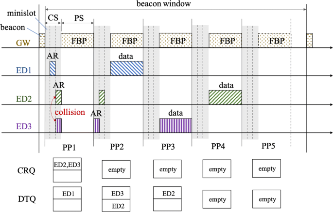
An example to illustrate the access procedure of FDQ-LoRa
-
In the first ping period (PP), three devices contend in the CS by sending access requests (ARs). ED1 succeeds while ED2 collides with ED3. After that, GW broadcasts a feedback packet (FBP) in the ping slot (PS). Note that there is no uplink data transmitted in this PS because DTQ is empty at that time. According to the feedback information, ED1 enters into the first position of DTQ, while ED2 and 3 enter into the first position of CRQ.
-
In PP2, ED2 and 3 contend in the CS, and they both succeed. In the ping slot, ED1 transmits its data, and GW broadcasts an FBP at the same time. ED2 and 3 receive the FBP, and they enter into the first two positions of DTQ according to the order of minislots.
-
In PP3, no device contends since the CRQ is empty at that time. ED3 transmits its data and GW broadcasts FBP in the PS. Note that in addition to the states of minislots, this FBP contains the acknowledgement to ED1’s data.
-
In PP4, still no device contends in the CS. ED2 transmits data, and GW broadcasts FBP.
-
In PP5, no contention and no uplink transmission exist; however, GW would broadcast FBP in this PS if it has response to ED2.

More explanations about our design are given in the following.
-
The BW is adaptive to the number of collisions, which means all collisions occurring at the beginning of a BW would be resolved before the next BW. GW informs all EDs about the BW interval through the beacon signal, and this time interval is estimated from the previous BWs. If the BW is longer than the native one (usually 128 s in LoRaWAN class B [18]), new synchronization information could be carried in FBP to keep EDs synchronized with the network.
-
For the native LoRaWAN class B, every ED should wake up in each PS for downlink reception. In our proposal, EDs only wake up for FBP reception in the PSs before its data transmission, and they keep sleeping in the PSs after completing data transmission. Note that if one ED needs acknowledgement, it wakes up for one more PS. This policy is benefit for energy savings.
-
Some device’s data transmission would interfere with the FBP reception of other devices, for example, in PP2, the FBP reception at ED2 is interfered by the transmitted signal of ED1. If the distance between ED1 and 2 is far enough, FBP still can be correctly decoded due to the capture effect [24]. However, if ED1 is close to ED2, correct decoding of FBP is obstructed. In this case, ED2 waits for the next CS to contend.
2.2.2 FBP structure
The FBP structure defined in [17] is modified in this paper. We add an extra response field, which is reserved for downlink acknowledgements and SF assignment information. This modification is preferred by reliability-dependent IoT applications where acknowledgements for uplink transmissions are demanded. As we mentioned before, it is also helpful to save energy and improve uplink throughput. Because the two receive windows for receiving downlink messages, specified in class A, can be removed. The new structure of FBP is depicted in Fig. 2.

FBP structure
As depicted in Fig. 2, the frame payload (FRMPayload) consists of three fields: (i) state field: state of CS (SoCS), ⌈2m/8⌉ bytes (m is the number of minislots); (ii) length field: lengths of two logical queues (LoQ), 4 bytes; and (iii) response field (RESP): acknowledgement and SF assignment, ⌈(3m+1)/8⌉ bytes. The reasons for the length of each part are as follows:
-
SoCS: Each minislot needs 2 bits to indicate its three kinds of states (success, collision, or empty) [23]; hence, the length is ⌈2m/8⌉ bytes when the number of minislots is m.
-
LoQ: Each logical queue is assigned with 2 bytes to indicate its length [17].
-
RESP: There are six available SFs, and the number of successful devices is no greater than m; thus, at most, 3m bits are required to indicate the SF assignments. Besides, another 1 bit is required for downlink acknowledgement. Hence, the total length is ⌈(3m+1)/8⌉ bytes.
According to LoRaWAN specification, the length of FBP PHYPayload is 17+⌈m/4⌉+⌈(3m+1)/8⌉ bytes. Then, the number of payload symbols can be calculated by [25]:
where PL is the number of payload bytes (1–255), IH indicates the header mode with 1 for header enabled and 0 for header disabled, DE=1 indicates the usage of data rate optimization and 0 otherwise, and CR is the coding rate (1 corresponding to 4/5, and 4 corresponding to 4/8). It is worth to mention that to make sure cell-edge devices can receive FBP, the GW uses SF12 to broadcast FBP. Besides, we set m=3, CR=1 (4/5), the preamble size to be 10.25 symbols, and use the implicit header mode. Hence, according to Eq. (1), the total length of FBP is 33.25 symbols, with the airtime TFBP to be 1.36 s (BW = 125 kHz). In addition, every device use SF12 to send AR before SF assignment, hence with the same parameter settings the interval of CS is TCS=3×0.08=0.24 ms (2-sym AR [17]).
3 Throughput analysis and transmission parameter optimization
3.1 System model
We consider a cell, whose radius is R km, in which one GW is located at the center and N EDs are uniformly distributed in the coverage of the cell (R2). The channel gain between each ED i (i∈{1,...,N}) and the GW is:
where g(t) is the small-scale fading gain, which can be modeled as an exponential random variable with unit mean (Rayleigh fading), and \(A(d_{i})=\left (f_{c}^{2}\times 10^{-2.8}\right)^{-1}d_{i}^{-\alpha }\) [26] is the path loss attenuation, with di the distance between ED i and the GW, fc the carrier frequency, and α the path loss exponent. The throughput performance will be analyzed in the next subsection.
The following are the assumptions:
-
The length of PS is fixed and the data transmission is error-free.
-
Every ED only has one data to send in a BW.
-
The number of minislots is no less than 3 (m≥3).
Note that it has been proved in [23] that with the assumption (c), the DQ protocol can achieve a maximum theoretical throughput approaching one and is stable for all input rate less than one.
3.2 Throughput evaluation
3.2.1 Normalized throughput with perfect SIC
In order to make all contending EDs wake up at the instant of CS, the CS duration (TCS) and PS duration (TPS) should be constant known values. According to Section 2.2.2, TCS is constant when m is predetermined (e.g., m=3,TCS=0.24 s). However, TPS is dependent on the airtimes of data and FBP, i.e., TPS= max{TDAT,TFBP}. Although TFBP is predesigned in Section 2.2.2 (1.36 s), TDAT is unknown. The reason is that for the same payload size, TDAT is distinct when using different SFs. Therefore, aiming at higher throughput and channel utilization, we permit EDs using different SFs to send data packets with different payload sizes and make TDAT close to TFBP.
For the available SFs, the corresponding TDAT and payload sizes (maximum 255 bytes) are listed in Table 1. Note that default SF assignment in this paper is based on the coverage range listed in Table 2 [26].
We define normalized system throughput as the average time of data packets occupied in the total used time, which can be represented as:
where N is the number of EDs, \(\overline {T}_{\text {DAT}}\) is the average airtime of a data packet, and n is the number of data-free PPs (e.g., PP1 in Fig. 1). \(\overline {T}_{\text {DAT}}\) can be obtained as:
where p(j) is the proportion of EDs that use SFj, which can be calculated as \(p(j)=\left (l_{j}^{2}-l_{j-1}^{2}\right)/R^{2}\), with lj and lj−1 the upper and lower bounds of the coverage range of SF j, respectively.
According to the analysis in [17], when m≥3 and N≥1000, data-free PPs are no more than 10% of data-existed PPs, i.e., n≤0.1N. Hence,
According to Eqs. (4) and (5), we obtain Snorm≥0.7 when α=2.7 and Snorm≥0.64 when α=4.
Note that we only estimate the lower bound of Snorm, since it is cumbersome to obtain an accurate closed-form expression of n, due to the stochastic access procedure. However, the stable high performance of DQ in densely loaded networks has been demonstrated [23, 27], and its throughput is independent of the number of EDs [17]. Therefore, in the next section, we will investigate the performance of FDQ-LoRa in terms of average throughput.
3.2.2 Average throughput with imperfect SIC
As we expected, the intended signal received by the FD GW will be contaminated by self-interference. Therefore, sufficient amount of SIC must be implemented before signal demodulation.
The received signal-to-interference-and-noise ratio (SINR) after SIC can be expressed as:
where pt,prsi, and pn are the power of transmitted signal, residual self-interference, and noise, respectively. Since the reception of intended signal fails when SINR is below the reception threshold qj listed in Table 2, the outage probability about SF j can be expressed as:
We define average throughput as, considering the impact of residual self-interference, the normalized throughput in a PP multiplied with the successful probability:
3.3 SF and CR optimization
As we know, reliable communication on an FD channel is impacted by self-interference [20, 22], and the SF and CR pair (j,c) assigned for each ED i should be carefully selected. To maximize the ED’s bitrate, the parameter selection problem can be formulated as:
where Rb=jc·bw/2j is the bitrate, and C=bw· log2(1+SINR) is the uplink channel capacity, with bw the bandwidth. Note that we only consider the uplink channel capacity since the downlink channel is free of self-interference.
4 Numerical results and discussions
4.1 Outage probability and average throughput
Simulation parameters are set under European regulations, i.e., fc=868 MHz, bw=125 kHz. The transmit power of ED is 14 dBm and that of GW is 20 dBm.
Figures 3 and 4 plot the curves of outage probability versus communication distance, under different SIC levels. As we can see, although Pout changes in a saw-tooth pattern among different SFs, however, when it comes to the same SF, Pout monotonously increases with the distance. Note that the saw-tooth pattern is caused by the distance-dependent reception threshold qj. In addition, higher SIC level contributes to lower outage probability, and to achieve the same Pout level, the required SIC level in urban scenario (α=4) is lower than that in sub-urban scenario (α=2.7). The reason is that the communication range in the urban is much shorter, which results in higher received power thus higher SINR before SIC.

Outage probability of FDQ-LoRa, in the sub-urban environment (α=2.7)

Outage probability of FDQ-LoRa, in the urban environment (α=4)
Figure 5 exhibits the average throughput of FDQ-LoRa (simply noted as FD) under different SIC levels, as well as the average throughput of our previous work [17] (noted as HD). We can observe that Savg of our proposal is improved when higher level SIC is performed, whereas when the level is higher than 75 dB (α=2.7) or 90 dB (α=4), no further improvement can be achieved. When SIC ≤ 50 dB and SIC ≥ 75 dB, the average throughput in the urban case is higher than that in the sub-urban case. It is rational since the urban case has lower Pout due to shorter communication distances. However, when 55 ≤ SIC ≤ 70 dB, the result becomes opposite. The possible explanation is that in the urban case, the probability of using SF7 is higher than the sub-urban case, and that of using SF12 is vice versa (shown in Figs. 3 and 4). This results in shorter \(\overline T_{\text {DAT}}\), thus lower Savg.

Average throughput comparison
On the other hand, the throughput of the HD scheme is constant against the SIC level, as it is free of self-interference. We can also observe that there exists a minimum required SIC level (60 dB in the sub-urban or 70 dB in the urban) to make our proposal superior than the HD scheme. When the SIC level is 100 dB, the proposed scheme achieves an extra improvement of 1.83-fold.
To investigate the performance of our proposal in the space-air-ground communications, the outage probability and average throughput under the distance beyond 100 km are also calculated, as shown in Figs. 6 and 7. It is worth to mention that, to accommodate our system model to the space-air-ground scenario, we modify the path loss model by changing the path loss exponent to 2. In addition, all EDs are enforced to use the same SF12 as the communication distance is very long. It can be observed from Fig. 6 that the outage probability increases faster with the incremental distance when the SIC level is lower. FDQ-LoRa is unusable in the space-air-ground scenario when the distance is higher than 180 km and the SIC level is 110 dB, because the outage probability is higher than 20%, whereas when the SIC level is up to 115 dB, FDQ-LoRa is applicable to the space-air-ground communications since the outage probability is always lower than 10%. Besides, the average throughput (in Fig. 7) is always higher than 0.8 when the SIC level is 115 dB. The results indicate that our proposal is applicable to the HAP-assisted space-air-ground communications.

Outage probability of FDQ-LoRa, in the space-air-ground scenario

Average throughput of FDQ-LoRa, in the space-air-ground scenario
4.2 Optimal SF and CR settings
We do the parameter pair (SF, CR) selection according to Eqs. (9a)–(9e) and the coverage restriction listed in Table 2, for SIC levels 20–110 dB and communication distances {1,5,10,15,20,25} km (α=2.7) and {0.1,0.5,0.6,0.7,0.8,1} km (α=4). Partial results are listed in Table 3. The first column is the SIC level, and the second and ninth rows are the communication distance.
From Table 3, at least 60-dB SIC level is required for cell-edge users to communicate with the GW when α=2.7. However, with shorter communication distances (i.e., α=4), only 20-dB SIC level is required to make the FD communication possible. This indicates that as an interference-resistant modulation techonology, LoRa is preferable for FD operation.
5 Conclusions
LoRa is a promising technology for IoT and space-air-ground communications due to its advantages in long-distance communication and anti-interference ability. It is desirable to address the scalability issue of LoRa networks, which comes from the Aloha-based MAC protocol adopted in LoRaWAN. To improve the throughput in a densely deployed LoRa network, we propose to combine DQ and FD technologies, by exploiting an FD-enabled gateway to schedule the transmissions of HD devices based on DQ mechanism. To accommodate the FD-enabled gateway, the access procedure and FBP structure are redesigned. Our design removes the receiving windows defined in class A, which is profitable for energy savings. The outage probability and average throughput are analyzed with imperfect self-interference cancelation. In addition, an SF-CR optimization method is also developed to maximize the bitrate, as well as make the cell-edge communications available. Simulation results show that our proposal attains an extra enhancement of 1.83-fold in throughput, and it is applicable to the LAP-assisted space-air-ground networks.
Availability of data and materials
The data that support the findings of this study are available on request from W. Wu. The data are not publicly available due to the information that could compromise research participant privacy and consent.
Abbreviations
- IoT:
-
Internet of Things
- DQ:
-
Distributed queueing
- IBFD:
-
In-band full-duplex
- LPWAN:
-
Low-power wide-area network
- PHY:
-
Physical
- MAC:
-
Medium access control
- SIC:
-
self-interference cancelation
- HD:
-
Half-duplex
- SF:
-
Spread factor
- CR:
-
Code rate
- ED:
-
End-device
- GW:
-
Gateway
- NS:
-
Network server
- BW:
-
Bandwidth
- TP:
-
Transmit power
- CRQ:
-
Collision resolution queue
- DTQ:
-
Data transmission queue
- AR:
-
Access request
- FBP:
-
Feedback packet
- CS:
-
Contention slot
- PS:
-
Ping slot
- PP:
-
Ping period
- SoCS:
-
State of contention slot
- LoQ:
-
Lengths of two logical queues
- RESP:
-
Response field
References
I. Lee, K. Lee, The Internet of Things (IoT): applications, investments, and challenges for enterprises. Bus. Horiz.58(4), 431–440 (2015).
L. Fernandez, J. A. Ruiz-De-Azua, A. Calveras, A. Camps, Assessing LoRa for satellite-to-earth communications considering the impact of ionospheric scintillation. IEEE Access. 8:, 165570–165582 (2020).
J. Haxhibeqiri, E. De Poorter, I. Moerman, J. Hoebeke, A survey of lorawan for iot: from technology to application. Sensors. 18(11), 3995 (2018).
N. Kato, Z. M. Fadlullah, F. Tang, B. Mao, S. Tani, A. Okamura, J. Liu, Optimizing space-air-ground integrated networks by artificial intelligence. IEEE Wirel. Commun.26(4), 140–147 (2019).
Y. Wang, Y. Xu, Y. Zhang, P. Zhang, Hybrid satellite-aerial-terrestrial networks in emergency scenarios: a survey. China Commun.14(7), 1–13 (2017).
A. Augustin, J. Yi, T. Clausen, W. M. Townsley, A study of LoRa: long range & low power networks for the internet of things. Sensors. 16(9), 1466 (2016).
The Things Network, LoRa world record broken: 832km/517mi Using 25 mw (2019). https://www.thethingsnetwork.org/article/lorawan-world-record-broken-twice-in-single-experiment-1. Accessed Mar 2021.
V, 1.0.3. LoRaWAN Specification. LoRa Alliance (2018).
F. Adelantado, X. Vilajosana, P. Tuset-Peiró, B. Martínez, J. Melià-Seguí, T. Watteyne, Understanding the limits of LoRaWAN. IEEE Commun. Mag.55(9), 34–40 (2017).
J. Liu, Y. Shi, Z. M. Fadlullah, N. Kato, Space-air-ground integrated network: a survey. IEEE Commun. Surv. Tutorials. 20(4), 2714–2741 (2018).
J. Haxhibeqiri, I. Moerman, J. Hoebeke, Low overhead scheduling of LoRa transmissions for improved scalability. IEEE Internet Things J.6(2), 3097–3109 (2019).
Z. Xu, J. Luo, Z. Yin, T. He, F. Dong, in IEEE INFOCOM 2020–IEEE Conference on Computer Communications. S-mac: Achieving high scalability via adaptive scheduling in LPWAN (IEEEToronto, 2020), pp. 506–515.
B. Reynders, Q. Wang, P. Tuset-Peiro, X. Vilajosana, S. Pollin, Improving reliability and scalability of lorawans through lightweight scheduling. IEEE Internet Things J.5(3), 1830–1842 (2018).
N. Kouvelas, V. Rao, R. R. V. Prasad, Employing p-CSMA on a LoRa network simulator (2018). http://arxiv.org/abs/1805.12263.
T. To, A. Duda, in 2018 IEEE International Conference on Communications (ICC). Simulation of LoRa in NS-3: improving LoRa performance with CSMA (IEEEKansas City, 2018), pp. 1–7.
K. Zhang, A. Marchiori, in 2017 IEEE International Conference on Pervasive Computing and Communications (PerCom). Crowdsourcing low-power wide-area IoT networks (IEEEKona, 2017), pp. 41–49.
W. Wu, Y. Li, Y. Zhang, B. Wang, W. Wang, Distributed queueing-based random access protocol for LoRa networks. IEEE Internet Things J.7(1), 763–772 (2020).
D. Ron, C. J. Lee, K. Lee, H. H. Choi, J. R. Lee, Performance analysis and optimization of downlink transmission in LoRaWAN class B mode. IEEE Internet Things J.7(8), 7836–7847 (2020).
J. G. López-Puigcerver. Hybrid arq scheme using in-band full-duplex LoRa (Universidad Politécnica de Madrid (UPM), 2018).
A. Sabharwal, P. Schniter, D. Guo, D. W. Bliss, S. Rangarajan, R. Wichman, In-band full-duplex wireless: challenges and opportunities. IEEE J. Sel. Areas Commun.32(9), 1637–1652 (2014).
L. Tian, S. Wang, Z. Cheng, X. Bu, All-digital self-interference cancellation in zero-if full-duplex transceivers. China Commun.13(11), 27–34 (2016).
K. E. Kolodziej, B. T. Perry, J. S. Herd, In-band full-duplex technology: techniques and systems survey. IEEE Trans. Microw. Theory Tech.67(7), 3025–3041 (2019).
W. Xu, G. Campbell, in SUPERCOMM/ICC ’92 Discovering a New World of Communications. A near perfect stable random access protocol for a broadcast channel (IEEEChicago, 1992), pp. 370–374.
N. E. Rachkidy, A. Guitton, M. Kaneko, Collision resolution protocol for delay and energy efficient LoRa networks. IEEE Trans. Green Commun. Netw.3(2), 535–551 (2019).
Semtech Corporation, SX1272/3/6/7/8: LoRa modem design guide. Semtech Corp. (2013).
L. Amichi, M. Kaneko, E. H. Fukuda, N. El Rachkidy, A. Guitton, Joint allocation strategies of power and spreading factors with imperfect orthogonality in LoRa networks. IEEE Trans. Commun.68(6), 3750–3765 (2020).
X. Zhang, G. Campbell. Performance analysis of distributed queueing random access protocol—DQRAP. Technical report (Department of Computer Science, Illinois Institute of TechnologyChicago, IL, USA, 1993).
Acknowledgements
The authors would like to thank the anonymous reviewers for their valuable comments and suggestions that helped improve the quality of the manuscript.
Funding
Not applicable.
Author information
Authors and Affiliations
Contributions
All authors have contributed equally to this work. All authors have read and approved the final manuscript.
Corresponding author
Ethics declarations
Competing interests
The authors declare that they have no competing interests.
Additional information
Publisher’s Note
Springer Nature remains neutral with regard to jurisdictional claims in published maps and institutional affiliations.
Rights and permissions
Open Access This article is licensed under a Creative Commons Attribution 4.0 International License, which permits use, sharing, adaptation, distribution and reproduction in any medium or format, as long as you give appropriate credit to the original author(s) and the source, provide a link to the Creative Commons licence, and indicate if changes were made. The images or other third party material in this article are included in the article’s Creative Commons licence, unless indicated otherwise in a credit line to the material. If material is not included in the article’s Creative Commons licence and your intended use is not permitted by statutory regulation or exceeds the permitted use, you will need to obtain permission directly from the copyright holder. To view a copy of this licence, visit http://creativecommons.org/licenses/by/4.0/.
About this article

Cite this article
Wu, W., Wang, W., Wang, B. et al. Throughput of distributed queueing-based LoRa for long-distance communication. EURASIP J. Adv. Signal Process. 2021, 28 (2021). https://doi.org/10.1186/s13634-021-00739-1
Received:
Accepted:
Published:
DOI: https://doi.org/10.1186/s13634-021-00739-1