- Research
- Open access
- Published:
Systematic design of transmitter and receiver architectures for flexible filter bank multi-carrier signals
EURASIP Journal on Advances in Signal Processing volume 2014, Article number: 103 (2014)
Abstract
Multi-carrier (MC) signaling is currently in the forefront of a myriad of systems, either wired or wireless, due to its high spectral efficiency, simple equalization, and robustness in front of multipath and narrowband interference sources. Despite its widespread deployment, the design of efficient architectures for MC systems becomes a challenging task when adopting filter bank multi-carrier (FBMC) modulation due to the inclusion of band-limited shaping pulses into the signal model. The reason to employ these pulses is the numerous improvements they offer in terms of performance, such as providing higher spectral confinement and no frequency overlap between adjacent subcarriers. These attributes lead to a reduced out-of-band power emission and a higher effective throughput. The latter is indeed possible by removing the need of cyclic prefix, which is in charge of preserving orthogonality among subcarriers in conventional MC systems. Nevertheless, the potential benefits of FBMC modulations are often obscured when it comes to an implementation point of view. In order to circumvent this limitation, the present paper provides a unified framework to describe all FBMC signals in which both signal design and implementation criteria are explicitly combined. In addition to this, we introduce the concept of flexible FBMC signals that, unlike their traditional MC counterparts, do not impose restrictions on the signal parameters (i.e., symbol rate, carrier spacing, or sampling frequency). Moreover, our framework also proposes a methodology that overcomes the implementation issues that characterize FBMC systems and allows us to derive simple, efficient, and time-invariant transmitter and receiver architectures.
1 Introduction
Multi-carrier (MC) signals are present in a myriad of applications such as high-speed digital subscriber lines [1], wireless communications [2], and wireless positioning [3, 4], just to mention a few. From a digital broadcasting perspective, MC signals are used in many standards such as the Digital Video Broadcasting (DVB-T [5], DVB-T2 [6], DVB-SH [7], and DVB-RCT [8]), Digital Audio Broadcasting (DAB) [9], and Digital Multimedia Broadcasting (DMB) [10], where orthogonal frequency-division multiplexing (OFDM) is the most widespread format of MC signaling adopted therein. In the recent years, though, there has been a growing interest in filter bank multi-carrier (FBMC) signals as an alternative to conventional MC signaling based on OFDM [11]. Compared to the latter, FBMC can be understood as a generalized signaling scheme that allows the replacement of the rectangular shaping pulse by a band-limited one. This property provides a more robust performance in front of carrier frequency mismatches, multiple access, and narrowband interferences. In contrast to what occurs in OFDM, FBMC signals can be designed so as to preserve the subcarrier orthogonality in multi-path propagation without necessarily requiring the insertion of a cyclic prefix. This advantage, together with the reduction of out-of-band power emissions [12], allows FBMC signals to enjoy higher spectral efficiency than the one provided by OFDM, which is especially attractive for band-limited systems. However, the obtained efficiency improvement in the frequency domain comes at the expense of longer pulses in the time domain, which overlap one with each other because their duration exceeds the symbol time. As a result of this overlap, many challenges do appear in the practical implementation of FBMC transceivers as compared to their OFDM counterparts [13], thus resorting to the use of advanced filter bank architectures.
Apart from implementation issues, another concern with FBMC signals is the wide range of FBMC variations that can be found in the literature, such as filtered multi-tone (FMT) [14], cosine modulated multi-tone (CMT) [15], discrete wavelet multi-tone (DWMT) [16], or offset quadrature amplitude modulated OFDM (OQAM/OFDM) [17]. Each of these variations uses a case-specific signal model as well as some restrictions over their signal parameters, thus making it difficult to address the design of transmitter and receiver architectures in a systematic way, as well as to perform a fair comparison among all possible FBMC alternatives. Moreover, the need for adjustable multi-rate architectures is currently emerging in FBMC-based cognitive radio, thus pushing filter bank architectures and FBMC signaling schemes beyond the limits of their initial designs [18–20]. In that sense, one of the goals of this work is to bridge the gap between existing variations of FBMC signals and a unified formulation capable of encompassing any FBMC scheme as a particular case of a generic and unconstrained FBMC signal model.
Attempts to do so have already been made in the existing literature [13, 21]. Nevertheless, most contributions on unified FBMC signaling formats are circumscribed to the study of analysis and synthesis filter banks, namely, in the context of image processing [21] or speech coding [22], where a single-carrier signal is typically undergoing some kind of sub-band processing [23]. The application of these signaling formats to the field of digital multi-carrier communications is not straightforward, since the conceptual approach is completely different here (i.e., the order of analysis and synthesis operations is inverted [24]) and new signal parameters, design constraints, and performance metrics do appear [25, 26]. Due to the lack of consensus in the FBMC signal definition, research efforts are being devoted to provide a suitable and generalized formulation for communications-oriented filter bank modulations [27]. An example of it is the so-called generalized multi-carrier (GMC) signal model [28], which considers all MC signals as subclasses of a unique signal model. A similar example is the case of non-orthogonal frequency division multiplexing (NOFDM), where neither the number of subcarriers, their spectral spacing, the shaping pulse (and its length), nor the symbol rate are specified [29–31].
Unlike previous contributions, our work is not merely focused on the definition of a generalized signal model. Instead, it aims at linking both signal design and implementation aspects of FBMC signals. To do so, we propose to parameterize FBMC signals by a set of key and common attributes. This generic parameterized scheme allows a free optimization of the signal so as to fulfill certain predefined criteria in terms of out-of-band radiation, power/bandwidth efficiency, physical layer security, synchronization performance, or implementation complexity. All these aspects highlight the importance of the general scope of our contribution and the necessity to avoid an exclusive focus on the well-known OFDM or other case-specific schemes, which might be suboptimal in many practical cases.
The general scope of our work, and the interest in encompassing the largest possible amount of different FBMC signals, is in contrast to traditional contributions on FBMC signaling. Typically, most works such as [21] and [32] do not consider all possible FBMC signals but only a small subset thereof, where simple implementations can easily be derived [27]. Other works like [14, 33, 34] do address those intricate cases, but the resulting architectures entail time-varying filtering coefficients, which require an unnecessary complex control and operation of memory buffers. The authors in [35] have come up with efficient architectures for some of theses intricate cases, but the overall process is specifically tailored to these signals, thus lacking a systematic derivation and general applicability in practice. In contrast, we address herein the efficient implementation of unfavorable types of FBMC signals that have been either eluded, partially addressed, or solved by time-variant schemes in the literature to date.
Since the emphasis is placed here on FBMC communication systems, our designs are parameterized by communication and signal-level parameters such as the symbol period or the subcarrier spacing. Moreover, we are interested on the impact these parameters have from an architectural point of view, in order to determine up to which extent a given combination of these parameters leads to feasible or unfeasible hardware implementations. This is contrast to most existing contributions, where the underlying structure of FBMC communication signals is typically ignored and where the focus is placed on efficient filter designs with the aim of achieving the perfect reconstruction (PR) property [36, 37] (i.e., as pursued in non-communication applications such as speech coding). It is interesting to note that the PR property is not a mandatory feature in wireless applications, since an additional equalization stage is actually needed at the receiver side to compensate for the frequency selective wireless channel [38, 39].
In summary, the main contributions of the present work are the following. First, we provide a unifying formulation that allows a compact parametrization of any FBMC signal out of a reduced set of parameters. Second, we offer a detailed methodology to derive flexible and computationally efficient architectures stemming from our unified formulation. Third, we obtain time-invariant schemes even in those challenging cases where signal parameters are not favorable from an implementation viewpoint. That alleviates the computational complexity of those cases for which time-variant architectures have been usually proposed. Additionally, we show how to obtain equivalent architectures for any FBMC signal, thus enabling a tailored design of the user and network terminals according to some performance requirements.
The remainder of this paper is organized as follows. A unified framework is proposed in Section 2, where any generic FBMC signal is mapped onto a quadruple of signal’s key parameters. Some multi-rate techniques and basic filter-bank theory are reviewed in Section 3 in order to support the derivation of flexible FBMC architectures as a function of such parameters. Section 4 provides implementation guidelines, through the extensive use of polyphase filters, along with the derivation steps that enable a transition from the signal formulation to the final transmitter architectures. An analogue reasoning is employed in Section 5 to derive the dual receiver architectures. Both transmitter and receiver architectures are presented for different types of polyphase network layouts and arbitrary signal parameter sets. Finally, an analysis of the computational complexity of the architectures is provided in Section 6.
2 Signal model and parametrization of flexible FBMC signals
In this section, we formulate a signal model that is flexible enough to encompass all existing MC signal formats by properly selecting the values of a few key parameters. Before doing so, we provide in Table 1 a reference list with the most important signal-level parameters, and in Table 2 a reference list with the key notation and mathematical operators is used throughout this work. These tables are provided for the sake of clarity and to help the reader follow the technical content of this paper.
2.1 Signal model of transmitted and received flexible FBMC signals
Let us consider the following continuous-time baseband equivalent model for an FBMC signal made up by N subcarriers with a frequency separation of
where are the symbols to be transmitted (in general, ), g(t) is the shaping waveform, R=1/T is the signaling rate (i.e., T is the MC symbol period), and φ n (l) is a possibly additional phase term used in some cases to ensure that the symbols are separable at the receiver. For instance, in OQAM/OFDM a 90° rotation is alternatively applied in the frequency and time dimensions (which are represented by indexes n and l, respectively) to force that the symbols adjacent to a real one are imaginary, and vice versa. In order to simplify the notation, we can gather the symbols and the additional phases into an equivalent symbol term . The signal model in (1) can also be used to represent MC-based offset modulations (i.e., those relying on offset quadrature phase shift keying (OQPSK) or minimum phase shift keying (MSK), on a per subcarrier basis). In that case, it is only necessary to interpret T as half of the actual symbol period.
The analog signal propagating through the channel is evidently independent of any sampling frequency. However, we are interested in both transmitter and receiver digital architectures, so we formulate the discrete-time version of the transmit signal in (1) sampled at a rate :
where the fundamental subcarrier discrete-time period (i.e., expressed in samples) is , N is the number of active subcarriers, and is the number of samples per MC symbol. The discrete-time shaping pulse is also called prototype filter, it is real-valued and has a length of L g =FsT g samples with T g the duration of its impulse response. Finally, L g , P and Nss are considered to be integer values.
One of the main characteristics of MC modulation systems resides on the fact that a total of N source symbols s n [l] are involved in the generation of a single MC symbol. Normally, such source symbols are strictly associated to N subcarrier frequencies. Hence, that leaves us with P−N subcarriers that are not associated to any source symbol conveying actual information, and therefore they are referred to as virtual subcarriers. The role of these subcarriers is typically to improve the spectral confinement and to facilitate carrier synchronization at the receiver end.
Following the same notation as in the transmit signal model, it is possible to formulate the discrete-time signal model of the reconstructed MC source symbols from a received signal x[m]. The reconstructed symbols associated to the n th subcarrier can be expressed as
At this point, it should be mentioned that depending on the configuration of the transmitter and receiver architecture, the reconstructed symbols may differ from the transmitted source symbols. That is the reason why the notation has been used in (3). If the designed schemes do not ensure a proper time and frequency orthogonality, this can lead to inter-symbol interference (ISI) and/or inter-carrier interference (ICI) even in the absence of noise. In those cases, an additional equalization would be required at the receiver end in order to eliminate these intrinsic interferences [14, 40].
Once the signal model has been introduced, it can be seen that (2) and (3) result from the conventional FBMC transmitter and receiver architectures depicted in Figure 1. The concatenation of the transmission and reception structures is also known as transmultiplexer[41] and it was originally created to transform time-division multiplexed (TDM) systems into frequency division multiplexing (FDM). In this work, we assume that the shaping pulse coefficients are real and have even symmetry. Therefore, the expression in (3) corresponds to the right-hand side of the scheme in Figure 1, given that g∗[−m]=g[m].

Conventional architecture for a flexible FBMC transmitter (left) and receiver (right). It can be observed that neither the number of input signals, the upsampling factor, nor the subcarrier period need to be the equal to one another.
2.2 Parametrization of flexible FBMC signals
Both in transmission and reception, the format of a flexible FBMC signal can be defined by four critical parameters or a combination thereof. In particular, we consider the quadruple:
where both the continuous-time and the discrete-time versions are provided in (4) for the sake of clarity.
The flexibility of the proposed model comes from the fact that any MC signal can be represented by a set of specific values of these four parameters . The parameter D can be regarded as the oversampling factor, representing the ratio between the sampling frequency Fs and the total MC symbol rate RN. This leads to in continuous-time, or equivalently, in discrete-time notation. In turn, the parameter Q represents the subcarrier spacing normalized to the symbol rate, in continuous-time, or equivalently, in discrete-time notation. Note that the minimum spacing that makes subcarrier orthogonality possible corresponds to Q=1. Moreover, since Q can take non-integer values, this model is also valid for the representation of non-orthogonal or generalized MC signals. Finally, represents the prototype filter length normalized to the subcarrier period, thus leading to in continuous-time, or equivalently, in discrete-time notation.For the sake of clarity, Figure 2 illustrates two different setups of FBMC signals where their different frequency-domain characteristics have been mapped onto the applicable parameters of the quadruple in (4). The following additional examples will further illustrate how the quadruple of parameters relates to the FBMC signal characterization:
-
Example 1. OFDM with N subcarriers where a fraction d of the symbol time is devoted to the cyclic prefix. This is a paradigmatic case of OFDM signaling where the signal is typically sampled at N samples per subcarrier period, leading to P=N. Moreover, both the symbol period and the OFDM rectangular pulse shape length become Nss=L g =(1+d)N. The resulting signal can thus be characterized by . If a null guard interval was used instead of the cyclic prefix, the representation would be {N,1+d,1+d,1}.
Figure 2 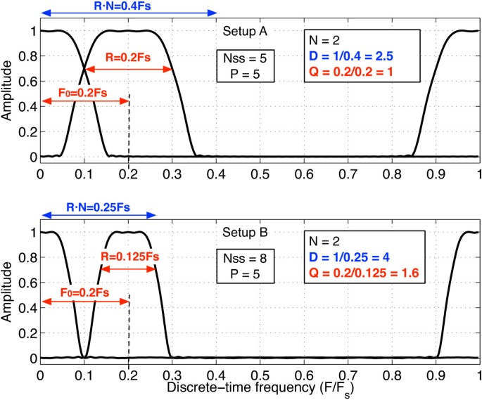
Frequency-domain interpretation of parameters { N , D , Q } in ( 4) for two different setups of MC signals. A fixed value for is assumed.
-
Example 2. FBMC signal with square-root raised-cosine (SRRC) shaping pulses whose length is limited to L g , a roll-off factor ? and a one-sided bandwidth equal to . Let us first consider the case of N subcarriers with separation F0=R and overlapping each other at the amplitude level. Then, assuming the Nyquist condition is fulfilled, a minimum sampling frequency of would be required to avoid incurring in aliasing. This involves having and , leading to . Let us consider next a different case with non-overlapping subcarriers. To do so, we would need a minimum subcarrier spacing of equal to twice the one-sided pulse bandwidth, leading to F0=(1+?)R. If we want to preserve the same number of subcarriers N as in the previous case, we need to increase the sampling frequency up to a minimum of Fs=N(1+?)R, thus oversampling by a factor . This setup would correspond to an FMT signal whose quadruple becomes .

This formulation has the advantage of making apparent that, for instance, FMT is very similar to OFDM from a structural point of view, but FMT simply uses a longer shaping pulse.
3 Multi-rate preliminaries for FBMC modulations
The processes of FBMC signal transmission and reception usually require several rate conversion operations between the multiplexed signals and the different subchannels. This is similar to what happens in MC demultiplexer/demodulators (MCDD) in satellite broadcasting [42], in cable TV channelizers [43], or in time-division to frequency-division multiplexing (TDM-to-FDM) [44], where several users and data streams are channelized into different subbands of the transmission bandwidth. The efficient implementation of such user and rate adaptation is done through the so-called polyphase architectures, which allow a significant reduction of the overall complexity by reordering the way down-conversion and filtering operations are carried out in traditional transceivers. Interestingly, polyphase architectures lead naturally to parallel architectures where intensive and high-rate computations are converted into a series of simple and low-rate simultaneous operations. For the case of high-rate filtering, the efficient implementation is based on the so-called filter banks, which are nothing but a bank of parallel short-length filters implementing the equivalent filtering operation at a much lower clock rate [45]. It is interesting to note that multi-rate filter bank systems are widely adopted in DVB satellite transponders [46], which can be understood in general terms as a multi-user multi-carrier system. For the case of flexible FBMC communication systems, in which a single user has actually allocated multiple carriers, the application of traditional filter bank architectures is not straightforward. The reasons are the different signal parameters, design constraints and performance metrics of these systems, and the actual impact of coherently processing several subcarriers at the signal level (e.g., the impact in terms of latency across subcarriers or the resulting mean square bandwidth, which is of interest for positioning applications). In view of this limitation, a dedicated study is required in order to come up with efficient architectures enabling FBMC communication as well as positioning systems. To this end, we will start first by briefly reviewing the basics of multi-rate digital signal processing and filter banks theory [47], and then we will proceed by presenting the proposed schemes enabling both transmit and receive architectures for FBMC communication systems.
As a previous step to the derivation of efficient flexible FBMC architectures, it is advisable to gain more insight in rate conversion operations and their interaction with finite impulse response (FIR) filters. Additionally, we will introduce here a notation for rate conversion operations accompanying digital filters that will be extensively used in forthcoming sections.
3.1 Interpolation and decimation filters
As it can be seen in Figure 1, the straightforward implementation of a FBMC system is highly inefficient from a computational point of view. For instance, the convolution between each subband signal and the prototype filter g[m] is carried out at the highest sampling rate, each convolution involves all the prototype filter coefficients and must be replicated for all subcarriers. Fortunately, multi-rate digital signal processing provides us the tools for reducing the computational requirements both in terms of clock rate and memory resources, thus leading to efficient architectures [48]. Interpolation and decimation are two of these tools, and they are extensively used in the present work. Let us first start by introducing the so-called interpolation filter, which operates with some arbitrary input signal u[m], whose rate has been increased by a factor B, and provides an output signal y[m] after convolution with a FIR filter g[m]. This operation is schematically represented in Figure 3. Mathematically, we can express y[m] as

Block diagram of an interpolation filter.
where the notation denotes that the upsampling operation by a factor B is carried out before the filtering operation. Analogously, a decimation filter can be defined as a digital filter followed by a downsampling operation by B, whose output can be expressed as
with the notation for the downsampling operation by a factor B. This is the result of the convolution between u[m] and g[m], as it is shown in Figure 4.

Block diagram of a decimation filter.
3.2 Complementary sampling rate conversion schemes
It is worthwhile introducing the complementary cases to the interpolation and decimation filters introduced in subsection 3.1. Let us first start by the time-domain expression of a filter followed by an upsampling operation (Figure 5):

Block diagram of a filter followed by an upsampler.
where for m=k B with and otherwise. Analogously, the output of a filter preceded by a downsampling operation (Figure 6) is given by

Block diagram of a filter preceded by a downsampler.
Using these concepts, a quick inspection of (2) reveals that x[m] is generated by adding up N different signals s n [l] after their convolution with the interpolation filter g[m], whose interpolation factor is Nss, and then modulated by a different exponential term associated to each subcarrier frequency. This sequence of operations in (2) is indeed represented in the scheme shown in the block diagram of Figure 1, which is the straightforward but inefficient implementation of a FBMC system.
3.3 Preliminaries of polyphase structures
The basic idea behind polyphase theory is that coefficients of both interpolation (5) and decimation filters (6) can be decomposed into B subsets of coefficients called subfilters, where B is referred to as the order of the polyphase network [49]. The decomposition of the decimation filter is called type 1, whereas the one corresponding to the interpolation filter is called type 2. In both cases, the coefficients of the i th subfilter, i∈{0,1,…,B−1}, are defined by the expression g i [m]=g[m B+i]. The main interest of the polyphase concept for MC signals comes down to the fact that subfilter coefficients may be associated to a unique exponential term in the convolution operation. Therefore, unlike conventional transmultiplexer implementations, it becomes no longer necessary to execute convolution operations for each subcarrier and involve the whole shaping pulse. On the contrary, they will be reduced to convolutions between subfilters and sets of samples of the input signal.
As a consequence of this rearrangement, the rate of each polyphase component is B times lower than the serial signals u[m] and y[m], and each subfilter is also B times shorter than the prototype filter. Both facts highlight the implementation efficiency benefits of this approach. Finally, and because of the modular (i.e., circular) structure of polyphase decompositions, we can exploit the cyclic (i.e., periodic) behavior of the complex exponentials in (2) and (3). This will allow us to make an extensive use of the DFT operation, and thus to further benefit from the efficient computation properties of fast Fourier transform (FFT) processors [50].
4 Efficient FBMC transmitter architectures
So far we have introduced the structures required to transmit and receive FBMC signals and how the filter bank theory can be used to improve the efficiency of such structures. Furthermore, we have shown that different types of FBMC signals can be obtained from a generic signal model characterized by a set of four signal parameters. In this section, we introduce a unified framework that connects all these elements in the form of a systematic architecture derivation for flexible FBMC transmitters with arbitrary signal parameters. A conceptual representation of the architectures that will be presented herein is schematically depicted in Figure 7. The proposed framework allows the particularization of the different parts of the system by means of a proper design of a polyphase network and a matching network. The main purpose of the matching network is to adapt the sampling rates of the signals delivered by the IDFT block to the ones required by the filters that make up the polyphase network.

General architecture for a flexible FBMC transmitter.
Apart from the quadruple of key signal parameters described in Section 2, FBMC architectures are determined by an additional parameter: the order of the polyphase network B. Different choices of B can be adopted at either the transmitter or the receiver end, so the subscripts t and r are adopted herein to indicate transmission and reception, respectively. Typically, the following values of B have been adopted in the literature: B x ={lcm(P x ,Nss),L g } where x={t,r} and lcm stands for least common multiple. However, a more general approach suggests a wider range of possibilities. In particular, we consider the following set of values for our study:
Such values represent the most significant examples from an architectural point of view. Architectures for other pairs of values (Bt,Br) can be easily derived following the steps presented in this section. That is the case of (Bt,Br)=L g for instance, for which the followed methodology would yield architectures based on polyphase subfilters of unitary length. It is important to mention that the matching network module in Figure 7 usually requires interpolation operations by a factor Q, which can be easily accommodated as long as Q is an integer number. The implementation for rational values of Q becomes challenging and it can be shown that the role of these interpolation modules would lead to time-variant input-output responses of the polyphase network when conventional methods are used [14, 33, 34]. In this work though, we show that it is possible to obtain efficient and time-invariant architectures for any value of Q, thus enabling a much simpler and cheaper implementation of FBMC user and network terminals. Addressing the extra complexity entailed by rational values of Q, which are usually avoided in practice, is one of the main contributions of this paper.
4.1 Efficient transmitter architectures for integer values of Q
First of all, we introduce the transmitter architectures obtained for integer values of Q, which are conceptually simpler in terms of implementation. The advantages of polyphase structures become apparent in this case since it is possible to obtain a polyphase network of order Pt (i.e., the very same number of transmitted subcarriers) that minimizes the required amount of hardware. For an arbitrary quadruple of design parameters, we can express the reference transmission signal model (2) as follows:
At this point, it can be observed in (10) that a Pt-point IDFT operation over the source symbols appears naturally. We are assuming here that typically Pt≥N and we proceed to arrange the source symbols in an (N×1) vector: , where the superscript T denotes the transpose operator. Likewise, we define the following notation for the IDFT operation: , which leads to the following compact expression of the signal model:
The above model, which extensively relies on the use of IDFT, was originally introduced by [51] and has been considered one of the catalysts in the success and widespread deployment of MC systems due to its efficient implementation through FFT processors. In that sense, one of the interesting features of polyphase structures is the exploitation of the cyclic nature of the IDFT/DFT exponentials, which leads us to introduce the modulo operation in the generated signal sample index in (11). Since any integer m can always be expressed as , we can rewrite (11) as follows:
Given that mod(m,Pt) takes the values {0,1,…,Pt−1}, we can consider that the signal in (12) implies a total of Pt different discrete-time convolutions, one associated to each value of mod(m,Pt). In terms of a polyphase decomposition, each of those convolutions will be associated to a different subfilter and consequently, to a different row in the polyphase network of Figure 7. Hence, we can regard the term mod(m,Pt) as a branch (or row) index that identifies the specific subfilter involved in the generation of the m th sample. Moreover, since each subfilter operates at a sampling rate Pt times lower than the serial signal x[m], we ought to apply a subfilter decimation by a factor of Pt over the prototype filter g[m]. We will henceforth make use of the notation introduced in (5) to rewrite (12) so that it explicitly reflects the mentioned manipulations:
where denotes the polyphase subfilter resulting from a -order decimation of the prototype filter g[m] with an offset of mod(m,Pt) samples:
The advantage of (13) is that it clearly outlines the series of operations that needs to be carried out for generating x[m] in an efficient manner. In particular, x[m] is the result of the convolutions of each IDFT output (upsampled by Q) with a downsampled version of the prototype filter followed by an upsampling operation by Pt. Therefore, there is a correspondence among the subfilters indexes defined in (14), the sample index of x[m], and the phase index on the IDFT output, thus leading to a rather intuitive architecture as depicted in Figure 8.

General architecture for a flexible FBMC transmitter with an integer normalized frequency spacing factor Q .
Note that the case of minimum frequency separation (Q=1) leads to the simplest possible polyphase architecture, where no upsampling operation would be required prior to the subfiltering operations. This example might correspond to the case of an OFDM modulation where no cyclic prefix has been added.
4.2 Efficient transmitter architectures for non-integer values of Q
We now move one step further by considering the more general case of any rational value of Q (i.e., when the subcarrier period and the MC symbol period do not share any common link). In that case, it follows from (13) that rational upsampling operations would be required prior to the subfilter convolution, thus complicating the design of time-invariant structures. The main implementation obstacle here is set by the rate imbalance between the symbol rate and the polyphase network output rate, which is given by the order of the polyphase network. In particular, a -order polyphase transmitter network generates blocks of Pt samples at its output (one for each subfilter). However, the number of samples per symbol generated should be Nss in order to meet the desired output rate of the digital communication signal being transmitted. In other words, if Q is not an integer, the symbol period in samples, Nss, does not account for an integer number of periods of the fundamental subcarrier frequency, thus making it hard to exploit the cyclic nature of the IDFT. Furthermore, since the duration of the symbol in samples is not a multiple of the order of the polyphase network, it would be necessary to apply a different set of filter coefficients to every symbol delivered by the IDFT block.
For these reasons, the implementation issues of this type of MC signals have been ignored in the literature or solved by means of time-variant schemes [33, 34]. In spite of these obstacles, we show in this work that if the polyphase and matching networks are properly designed, it is certainly possible to obtain a time-invariant structure for any rational value of Q. This clearly provides significant advantages, enabling complete freedom in the choice of the MC signal parameters that best suit the requirements of the application under consideration.
Regarding the architectures to be presented next, it should be noted that they are essentially equivalent in the extent that they generate the same signal, while merely differing in the layout of the polyphase and matching networks. The flexibility of the framework provided in this work is clearly highlighted by this fact, since any of these schemes can be used indistinctly depending on the specific constraints of the application of interest. Hereunder we present a derivation of such structures for the proposed polyphase orders Bt={Pt,Nss,lcm(Pt,Nss)}. This set of values of Bt will let us show the necessary steps required to derive any other architecture.
4.2.1 Order of the polyphase network Bt=Pt
For the sake of clarity, let us express the index of the convolution in (2) as a function of two subindexes: l=l b Pt+l r , being and . This decomposition is motivated by the order of the polyphase network Pt and allows us to introduce the term mod(l,Pt), which will serve as a row (or branch) index in the resulting polyphase network. Besides, there is a multiple-of- Pt term that acts as a sample index of the convolution operation for each subfilter. Then, we can rewrite (2) according to the notation introduced in (11) as follows:
Additionally, we can further decompose the term m−l r Nss according to the dual indexing that we will be permanently seeking throughout this paper, which consists in expressing the sample index as the sum of a multiple-of- Bt term plus a modulus-of- Bt residual. That leads us to
Therefore, we can rewrite x[m] applying the notation in (13) to reflect the -order subfilter decimation:
A careful analysis of (17) reveals some similarities with the transmitted signal expression in the case of integer Q shown in (13). In this case though, there appears an additional delay term of l r Nss samples that affects each subfilter output as well as the subfilter indexes. Therefore, it is not possible to generate the transmit signal x[m] with a single -order polyphase structure like the one shown in Figure 8. However, it is actually possible to consider separately the architecture defined by each value of l r and deal with them as different parts of a bigger structure. These parts are actually polyphase networks of order Pt themselves that we will refer to as subnetworks. Therefore, the resulting scheme employs a total of Pt polyphase subnetworks of order Pt.
Moreover, the IDFT output must be downsampled by Pt and it is also subject to a variable sampling offset of l r samples that is constant for each subnetwork. Therefore, the samples delivered by the IDFT will be processed separately by different subnetworks within the entire polyphase network. This fact is reflected in the architecture through what we call a block-wise serial-to-parallel converter of order Pt. This module vertically concatenates Pt blocks of Pt samples as they are sequentially output by the IDFT. In addition, it should be noticed that in (17), the index of the polyphase subfilters mod(m−l r Nss,Pt) and the index of the IDFT output mod(m,Pt) will not coincide, as opposed to what happened in the case of integer Q. Then, in order to achieve a proper matching between the IDFT output and the polyphase network rows, it is necessary to compensate the unbalance of l r Nss samples between the subscript terms in (17). One possible way to do it is through the introduction of a phase rotation over the input source symbols s n [l]. Such a rotation will take place at the input of the IDFT and will produce a delay of the same amount of samples at its output. With this slight modification and by virtue of the Fourier transform properties, we are able to compensate the mentioned unbalance and we also make sure we are not altering the generated signal. Hence, let us define so that we obtain
Finally, we are left with the following expression for the transmit signal:
The final transmitter architecture shown in Figure 9 follows directly from (21). It is worth to observe that the phase rotation over the source symbols remains constant within each subnetwork because it is a function of the subnetwork index l r . Besides, according to the properties of the convolution, the delay of l r Nss samples in (21) has been readily moved to the subfilter outputs with no loss of generality.

-order polyphase architecture for FBMC transmitters with rational normalized frequency separation factor Q.
4.2.2 Order of the polyphase network Bt=Nss
The approach adopted in the previous case would lead to time-variant architectures for the present case of Bt=Nss. Since time-varying schemes is indeed what we intend to avoid in this work, a slightly different approach is required herein. To do so, let us decompose the output index of the convolution m into both a multiple-of- Nss term (m b ) and a modulus-of- Nss residual (m r ) according to the desired polyphase order. Therefore,
This decomposition by itself does not lead to the derivation of an efficient architecture, so we need to apply a further decomposition of the index m b as follows:
where and . We have also assumed that , being Pto an integer number as well. Replacing (22) and (23) in (11) we are left with:
Note that we have applied a subfilter decimation by Nss in order to obtain an -order polyphase structure. The associated subfilters are defined as .
It is important to highlight that the order of the polyphase network Nss is higher than the duration (in samples) of the subcarrier fundamental period Pt. That means that the number of polyphase rows is larger than the length of the IDFT output in the architecture. This asymmetry can be easily compensated by extending the length of the IDFT output to match the order of the polyphase network. In particular, we propose a solution based on the addition of the initial part of the symbol at the end of the first Pt samples, creating a cyclic extension of the IDFT output. These Nss−Pt extra samples can be seen as a cyclic prefix appended to the actual symbol that otherwise would have a duration of Pt samples (e.g., as if no redundancy was introduced). Indeed, there is a degree of freedom from a design point of view to fill up these samples at the last part of the symbol. Note that this clarification was not necessary in the previous case (subsection 4.2.1), since the length of the IDFT output and the order of the polyphase network coincided. Finally, it has to be considered that the values adopted here for the samples in the final part of the symbol are not unique. Other solutions like zero-padding or pilot signaling would be also valid and would not have any meaningful impact on the obtained architectures.
Additionally, due to the imbalance between the order of the polyphase network and the size of the IDFT, the phase continuity over time of the different subcarriers in (2) cannot be ensured with a single -order structure. This fact is highlighted in (25) where the subscripts of the IDFT output, mod(mb 2Nss+m r ,Pt), and the prototype filter, mod(m r ,Nss), do not match. Therefore, it is convenient to resort once more to a phase rotation over the input source symbols to ensure the signal phase continuity at every symbol transition. Let us then define the following equivalent IDFT output:
where represents a phase-rotated version of the source symbols. Using the results of (28) in (25) and expressing x[m] as a function of the output sample index m, we obtain
Now the indexes of the IDFT output and the subfilter coincide, although the range of variation of the IDFT indexes is restricted to Pt, which is precisely the motivation for the cyclic extension. The expression of the transmitted signal is
Finally, the resulting architecture can be built upon Pto polyphase subnetworks of order Nss as it is illustrated in Figure 10.

-order polyphase architecture for FBMC transmitters with rational normalized frequency separation factor Q .
4.2.3 Order of the polyphase network Bt=lcm(Pt,Nss)
Let us rewrite the polyphase order Bt as PtoNss=NssoPt=lcm(Pt,Nss), where both Pto and Nsso are integer numbers. Given that the order of the polyphase network is a multiple of the subcarrier period in samples Pt, we can proceed in this case as we did in subsection 4.2.1. Hence, we can conveniently decompose the convolution index as l=l b Pto+lr with and . Replacing (11) we obtain
As it was done in (16), we work with a decomposition of the term m−l r Nss according to the desired polyphase structure order PtoNss:
Then replacing (32) in (31) and applying a -order subfilter decimation, we obtain:
where . We can see that there appears again a shift of l r Nss samples in (33) at the subscripts of the prototype filter with respect to the IDFT output subscript. Following an analogous reasoning to subsection 4.2.1), we can write
Note that we have applied the same phase rotation over the source symbols as in (18). Besides, the block-wise serial-to-parallel converter now concatenates Pto blocks of size lcm(Pt,Nss) as it is shown in the resulting transmitter architecture depicted in Figure 11.

lcm( P t , N ss ) th -order polyphase architecture for FBMC transmitters with rational normalized frequency separation factor Q .
Analogously to the previous cases, the final architecture is made up of several polyphase subnetworks of order lcm(Pt,Nss), where the subindex l r can be seen as a subnetwork index for a total of Pto identical polyphase structures of order PtoNss. Note that although the ranges of variation of the subscripts in (34) do not coincide, the order of the polyphase networks is an integer number of fundamental carrier cycles. Hence, there is no need to include further phase corrections inside each network block. In other words, intra-block phase continuity is guaranteed by the design of the polyphase layout, whereas inter-block phase continuity is easily achieved by the above-mentioned phase rotation over the source symbols.
To conclude this section, it is important to highlight that we have presented a set of time-invariant FBMC transmitter architectures together with the necessary steps for their derivation starting from the unified signal model introduced in Section 2. These architectures are computationally efficient since they are based on polyphase decompositions of the prototype filter. Additionally, they allow us to implement FBMC transmitters for any configuration of signal parameters (i.e., for arbitrary subcarrier period P, symbol period Nss, pulse shape length L g , and normalized subcarrier spacing Q) just by using simple digital signal processing blocks such as up/down-sampling converters, filters, and sample delays. As already mentioned, no complicated circular shifts, temporary buffers, or memory swapping operations are required, which means a considerable simplification of those FBMC implementations where Q is rational, which have been commonly ignored by the research community.
5 Efficient FBMC receiver architectures
In this section, we will make use of an analogous methodology to the one presented in Section 4 but placing the emphasis on the receiver side. Thus, our objective is to derive a general receiver architecture for any quadruple of FBMC signal parameters and the polyphase network orders introduced in (9). Similarly to what happened for the transmitter side, rational values of the normalized frequency separation factor Q also lead to non-integer downsampling operations, thus complicating the derivation of time-invariant architectures. Nevertheless, we will show that a parallel reasoning to the one in Section 4 enables polyphase layouts based upon time-invariant schemes even for non-integer values of Q.
Another aspect to be accounted for is the so-called reconstruction delay, which ensures the perfect reconstruction of the transmitted symbols at the receiver end [52]. This is a delay that needs to be incorporated as part of the transmission channel and whose motivation is to reflect the causality of the system. In particular, let us assume that the prototype filter length can be expressed as
where both α and β are integer numbers and Br is the order of the receiver polyphase layout. Then, it can be proven that the term β turns into a delay that affects the received signal x[m] while α becomes a sampling delay at the reconstructed source symbol sequences , as indicated in Figure 12.

General architecture for a flexible FBMC receiver where the concept of reconstruction delay is illustrated.
5.1 Efficient receiver architectures for integer values of Q
Let us start from the reference reception signal model for a FBMC transmultiplexer introduced in (3) but restricted to integer values of Q so that the reconstructed symbols can be expressed as
As it has been previously done, it is convenient to decompose the convolution index l into an integer term, multiple of the order of the polyphase network, and a modulus term of the same order. In this particular case, it is possible to obtain a receiver based on the simplest possible polyphase structure of order Pr. We can write and apply a -order subfilter decimation in (36). Then, we obtain
where and . Now, let us define
Then, we can store the samples in blocks of size Pr as follows:
so that (37) can be simplified to
where the operator denotes the n th output of the Pr-point DFT of a given sequence and the operator performs a downsampling operation by a factor Q over each component of the input vector. The resulting receiver architecture is depicted in Figure 13. Intuitively, it is easy to see that the particular case where Q=1 corresponds to an OFDM receiver with an arbitrary shaping pulse and no cyclic prefix addition. The only difference between both architectures would be the downsampling operation following the subfiltering of the received signal samples, which is not needed in OFDM. It should be noticed that filtering operations are carried out at a rate which is Pr times lower than the rate of the input signal, thus decreasing the computational cost of the receiver. As expected, a time-invariant architecture has been obtained with a minimum amount of hardware.

General architecture for a flexible FBMC receiver with an integer normalized frequency separation factor Q .
It is worthwhile mentioning that although the schemes obtained in transmission and reception are symmetrical, the methodology followed for their derivation has been slightly different. For example, the DFT operation in the reception schemes cannot be explicitly inferred from the signal model in (3) because the exponential term cannot be decoupled from the convolution operation as it was done in (11). Additionally, the final receiver architectures are obtained through the decomposition of the index of the convolution operation rather than the index of the output samples. These aspects add more complexity to the receiver manipulations with respect to Section 4 even though the final result may look similar.
5.2 Efficient receiver architectures for non-integer values of Q
As in transmission, rate imbalance issues do appear because of the mismatch between the symbol rate and the polyphase network order. Therefore, for the set of polyphase order values under consideration, Br={Pr,Nss,lcm(Pr,Nss)}, some modifications have to be performed over the standard polyphase structure in order to avoid a time-variant filtering.
5.2.1 Order of the polyphase network Br=Pr
We apply the same convolution index decomposition over the reference signal in (3) as in the case of integer Q. Hence, assuming that , we are left with
Now, we can apply an identical index decomposition over the output sample index so that . Replacing in (41) and applying a -order subfilter decimation we get:
Note that we have conveniently moved the delay term l r Nss towards the input signal x[m] without any loss of generality. So in order to assess the impact of this delay term on the architecture, we further decompose the term m r +l r Nss as follows: , yielding
It follows from (43) that the delay term l r Nss has a twofold impact: a variation of the row index (subscript) of the input signal x[m] on the one hand and an integer number of samples shift over its sample index on the other hand. However, these variations lead to a mismatch between the subscripts of the signals involved in the convolution in (43), namely, downsampled versions of x[m] and g[m] and the phase index of the DFT exponentials. Again, we will make use of the phase rotation concept introduced in (18) to balance out this mismatch. To that end, we rewrite (43) as
It is clear from (44) that the row delay of l r Nss samples is compensated by the phase rotation applied over the received source symbols (i.e., at the output of the DFT). Hence, we can redefine the vector y[k] in (39) to store blocks of Pr samples resulting from the outputs of the polyphase subfiltering:
where
Since l r ={0,…,Pr−1}, we can conclude that a total of Pt versions of the received signal, each delayed by l r Nss, will be processed separately giving rise to Pr polyphase subnetworks of a basic -order polyphase structure. That leads us to define a block-wise parallel-to-serial converter of order Pr that serially concatenates a total of Pr blocks of size Pr. Therefore, replacing (45) in (44), we are left with the following:
As expected, the receiver architecture shown in Figure 14 constitutes the dual scheme to the transmission case in Figure 9.

General P th -order polyphase architecture for a FBMC with a non-integer normalized frequency separation factor Q .
5.2.2 Order of the polyphase network
Again, we resort to a decomposition of the convolution index according to Br. Thus, we can express m as m=m b Nss+m r , where and . However, such a decomposition complicates substantially the derivation of a receiver architecture. The approach followed so far would lead to the following equation:
where and . It can be observed in (48) that there appears an exponential term, , that modulates the input signal and also depends on the subcarrier index n. Such a modulation term makes it difficult to turn the signal model into an efficient architecture.
Nonetheless, keeping in mind that lcm(Pr,Nss)=NssPro=N s s o Pr (where both Pro and N s s o are integers), we will further decompose the convolution index into m b =mb 1Pro+mb 2. Being and . Hence, we are left with three different convolution subindexes:
Through this additional decomposition, we can circumvent the problem induced by the modulating term in (48) and obtain an expression of the reconstructed symbol sequence that allows a direct transition to the final architecture. As a result of introducing (49) in (3) we are left with:
At this point, it is possible to apply now the -order subfilter decimation that we have been pursuing:
By means of the triple index decomposition in (49), the exponential term in (48) has turned into a mere phase rotation to be applied after the DFT operation in (51). The subfilter convolution output is now defined as:
being
Again, we are dealing with polyphase networks that are replicas of a basic polyphase structure of order Nss, where mb 2 can be interpreted as a subnetwork index. This takes us to the following compact expression:
The resulting architecture is depicted in Figure 15. As in the previous case, the obtained architecture corresponds to the dual scheme to the transmission architecture in Figure 10.

General -order polyphase architecture for a FBMC with a non-integer normalized frequency separation factor Q.
5.2.3 Order of the polyphase network Br=lcm(Pr,Nss)
In this case, we apply the index decomposition . Additionally, we are going to decompose the output sample index as follows: l=l b Pro+l r , being and . Then, replacing in (41) we obtain:
Once again, we choose to split up the delay term into to reflect that it affects not only the convolution index (i.e., a delay of a certain number of samples) but also that it entails a shift of a certain amount of rows. As a consequence of that, it is necessary to compensate such a delay with a phase rotation of the received symbols. Therefore, after an -order subfilter decimation we obtain
being . The output of the subfilter convolution is then given by
and these samples are arranged in blocks of size ProNss:
Thus, we can obtain the expression of the received signal:
The resulting architecture is depicted in Figure 16.

General l c m ( P r , N ss ) th -order polyphase architecture for a FBMC with a non-integer normalized frequency separation factor Q .
The conclusion of this section is that similarly to what happened for the transmitter, time-invariant efficient architectures can also be derived for a generic FBMC receiver with arbitrary signal parameters (i.e., either subcarrier period P, symbol period Nss, pulse shape length L g , and normalized subcarrier spacing Q). In all cases, the resulting architectures are just based on simple processing blocks and can be readily implemented in practice. It must be remarked, though, that depending on the selected transmit and receive filters, the reconstructed symbols may differ from the transmitted ones. This typically occurs when the composite end-to-end pulse shape response does not ensure proper time and frequency orthogonality, thus leading to inter-symbol and inter-carrier interference. This problem, which is out of the scope of the present work, requires an additional equalization stage in order to eliminate these intrinsic interferences affecting the recovered symbols . The interested reader is referred to the works in [14, 40] and the references therein, where a similar equalization problem has been addressed.
6 Complexity analysis
In order to perform a comparative analysis of the efficiency of each architecture with respect to the conventional transmultiplexer implementation, we have studied the computational complexity of each scheme. Since all the architectures presented in this work are equivalent from a functional point of view, the computational complexity becomes the main selection criteria for an actual implementation. Following the example of other works [53], we have taken the number of complex multiplications per multi-carrier symbol, NCM, as the primary complexity performance metric.
6.1 Complexity analysis of the conventional transmultiplexer
A closed-form expression of the computational complexity for the classical filter bank transmitter and receiver can be directly inferred by visual inspection of Figure 1. In particular, the NCM executed in the filtering process is given by the length of the shortest sequence involved in the convolution. We will assume that the input sequence is very long as compared to the length of the prototype filter g[m], as it happens for instance in data broadcasting systems. Therefore, we can state that the number of coefficients of g[m] determines the number of multiplications performed in each filtering operation. It is worth mentioning that following the reasoning in [54], we take the MC symbol time as our unit time reference for both transmission and reception. Furthermore, we should keep in mind that the up/down-sampling operations in Figure 1 would act as scaling factors over NCM only if we considered the sampling interval of the bandpass transmit signal x[m] as our reference unit time instead. Hence, we can conclude that for a generic FBMC transmultiplexer, NCM, is given by
and
where L g is the length in samples of the prototype filter (i.e., the shaping pulse g[m]). N CMt and N CMr are the numbers of complex multiplications (CMs) per symbol time carried out by the transmitter and receiver, respectively. Note that in the case of N CMt, the number of complex multiplications involved in the convolution with the prototype filter becomes rather than L g , where the operator ⌈x⌉ denotes the smallest integer greater or equal than x. The reason for this is the upsampling operation by Nss before the filter that introduces Nss−1 zero-valued samples for each sample of s n [l]. Similarly, the downsampling operation by Nss in the case of N CMr contributes to the second term in (61). For each subcarrier, it requires Nss samples of the received signal x[m] to reconstruct a multi-carrier symbol s n [l]. That means that between two consecutive samples of s n [l], there are Nss fresh samples of x[m] that have to be multiplied by the exponential term preceding the filter.
6.2 Complexity analysis of the efficient architectures for integer values of Q
The main difference between these architectures and the transmultiplexer is the introduction of the FFT blocks. For the analysis in this section, we have assumed that the number of points of the FFTs is always a power of 2. According to that assumption, we consider a Cooley-Tukey [55] implementation of the IDFT/DFT blocks for the architectures presented in previous sections. Assuming the worst case scenario, which implies using P out of P available subcarriers, a total of P·log2P complex multiplications are required for each FFT module. Thus, we can obtain from Figures 8 and 13 the following expressions:
and
Here the length of the subfilters is given by . The architecture in Figure 8 reveals that there are mainly two contributions to N CMt: the number of CMs performed by the IDFT (Ptlog2Pt) and the number of CMs performed due to the convolutions with the subfilters (), which is divided by Q due to the upsampling operation. However, this architecture generates blocks of Pt samples, so in order to generate a multi-carrier symbol, it is necessary to carry out the convolution operation Q times, namely, multiplying the convolution term by a factor Q, giving rise to Equation 62. An analogue reasoning has been followed to obtain the expression for N CMr in (63). Unlike the transmission case, the number of CMs executed in reception does not depend on factor Q since the samples discarded by the downsampling operation do not contribute to the reconstruction of the signal.
6.3 Complexity analysis of the efficient architectures for non-integer values of Q
Following the same logic as the previous architectures, we can conclude that
-
For Bt=Pt and Br=Pr, depicted in Figures 9 and 14, respectively, we have
(64)and
(65)Each polyphase subnetwork of order Pt in transmission generates blocks of Pt samples, but rather than the number of CMs per block, we are interested in the number of CMs performed for each multi-carrier symbol. It can be seen in Figure 9 that on average, a total of Pt subnetworks are involved in the generation of Pt MC symbols. Therefore, the number of CMs for of each symbol depends on those performed by each subnetwork in the polyphase structure.
-
For Bt=Nss and Br=Nss, depicted in Figures 10 and 15, respectively, we have
(66)and
(67) -
Here, for the calculation of N CMt and N CMr, we have taken into account that unlike the previous case, all polyphase subnetworks are simultaneously involved in the generation/reconstruction of a single multi-carrier symbol. That is why N CMr is Pto times the number of CMs performed by each subnetwork. This means a difference with the rest of the presented receiver architectures where the different subnetworks process sequentially blocks of Br samples that are then delivered to the DFT block.
-
For Bt=lcm(Pt,Nss) and Br=lcm(Pr,Nss), depicted in Figures 11 and 16, respectively, according to the mentioned criteria, we can state that
(68)and
(69)
A comparative analysis of these equivalent schemes has been performed based on the number of CMs carried out to generate and reconstruct a paradigmatic example of FBMC signal. In particular, we have addressed the case of an FMT transceiver since it is one of the most cumbersome FBMC modulations from an implementation point of view. As to digital broadcasting systems, FMT can be seen like a sort of frequency division multiple access (FDMA) technique, which is commonly used in satellite links [56]. FMT modulations give rise to non-integer values of the parameter Q which lead to complex architectures as we have seen before. We assumed a SRRC shaping pulse with a roll-off factor of ρ=1/2, a total of Nss=P(1+ρ) samples per symbol, an observation interval of 30 symbols, and a discrete time-domain length of the shaping pulse L g =10Nss. The expressions of NCM in transmission and reception have slight differences so we will analyze their complexity separately.
We have calculated the computational complexity of all the architectures as a function of Pt,r, which is the number of available subcarriers either in transmission or reception. We have chosen this parameter for our analysis because it is a magnitude directly related to the number of active subcarriers N, which usually varies in MC standards that implement a certain signal model. For the sake of simplicity, we have assumed that all available subcarriers will be used as active subcarriers (Pt,r=N) and a range of variation for Pt,r from 16 to 128 subcarriers.
The values of NCM for different transmitter and receiver architectures are depicted in Figures 17 and 18, respectively. At a first glance, it can be observed that polyphase-based architectures improve significantly the performance of the FBMC transmultiplexer in terms of computational complexity. More specifically, we define the complexity gain variable that will allow us to estimate the relative computational efficiency improvement achieved with each polyphase architecture with respect to the conventional transmultiplexer implementation:

Number of complex multiplication per unit time for different efficient FBMC transmitter architectures.

Number of complex multiplication per unit time for different efficient FBMC receiver architectures
where N CMtransmux is the number of complex multiplications per symbol time executed by the transmultiplexer and the subscripts {t,r} denote transmission and reception, respectively. The relative gain obtained by each architecture is shown in Figures 19 and 20.

Complexity gain G t with respect to the transmultiplexer for different FBMC transmitter architectures.

Complexity gain G r with respect to the transmultiplexer for different FBMC receiver architectures.
Among all presented receiver architectures, the case Br=Pr requires the minimum number of complex multiplications, as it can be observed in Figure 20. On the other hand, its reciprocal architecture in transmission entails the highest computational complexity whereas the case of Bt=lcm(Pt,Nss) provides the best performance among all transmitters. Therefore, although the higher the order of the polyphase structure, the shorter the polyphase subfilters, it does not necessarily translates into a lower number of CMs. This uneven behavior suggests that an asymmetric layout may be the optimum approach from a computational efficiency’s point of view. However, other applications that do not prioritize the computational speed of the system might be subject to different selection criteria for the most suitable polyphase layout. For example, if the goal is to minimize the amount of memory resources required to process the FBMC signal, polyphase structures with the shortest subfilters and a minimum amount of subnetworks should be sought both in transmission and reception. Hence, although the reduction of the computational complexity is the most common architecture selection criterion, other properties of the presented layouts could be easily assessed to find the one that better fits the application at hand.
7 Conclusions
In this paper, we have explored the potential of flexible FBMC schemes in providing a new design paradigm for digital communications architectures, as an alternative to conventional OFDM schemes. We have presented a unified framework to characterize any possible multi-carrier modulation, including those relying on band-limited shaping pulses. We have defined a general signal model and identified a set of four signal parameters whose values characterize the transmitted signal. Moreover, we have clearly exposed the main implementation obstacles prompted by certain combinations of such parameters, which have been systematically avoided or only partially addressed in the literature. Through the extensive use of the polyphase decomposition of the prototype filter and standard multi-rate techniques, we have been able to derive efficient transmission and reception architectures starting from the introduced signal model. Our contribution covers the gap existing in the literature between the signal model definition and the generation of the final architecture. Besides we also provide time-invariant architectures for all cases presented, thus avoiding the complexity of time-varying schemes that usually involve the dynamic operation of memory buffers and circular sample shifts. Finally, we perform a comparative assessment of the computational efficiency improvement obtained for each polyphase-based architecture with respect to conventional FBMC implementations.
References
Cendrillon R, Collings I, Nordstrom T, Sjoberg F, Tsatsanis M, Yu W: Advanced signal processing for digital subscriber lines. EURASIP J. Adv. Signal Process 2006, 1-3.
Gerakoulis D: Multicarrier access and routing for wireless networking. EURASIP J. Wirel. Commun. Netw 2005, 599-606.
Dai L, Wang Z, Pan C, Chen S: Wireless positioning using TDS-OFDM signals in single-frequency networks. IEEE Trans. Broadcast 2012, 58(2):236-246.
Wang D, Fattouche M, Ghannouchi FM: Multicarrier code for the next-generation GPS. EURASIP J. Wirel. Commun. Netw 2012, 1-22.
Jallon P: An algorithm for detection of DVB-T signals based on their second-order statistics. EURASIP J. Wirel. Commun. Netw 2008, 1-9.
Sugaris A, Reljin I: DVB-T2 technology improvements challenge current strategic planning of ubiquitous media networks. EURASIP J. Wirel. Commun. Netw 2012, 52: 1-14.
Bolea Alamanac A, Burzigotti P, Cohen M, De Gaudenzi R, Liva G, Lipp S, Pulvirenti O, Roullet L, Stadali H: Performance validation of the DVB-SH standard for satellite/terrestrial hybrid mobile broadcasting networks. IEEE Trans. Broadcast 2011, 57(4):802-825.
ACG de Carvalho Reis: Performance evaluation of the DVB-RCT standard for interactive services. IEEE Trans. Broadcast 2011, 57(4):840-855.
Shelswell P: The COFDM modulation system: the heart of digital audio broadcasting. Electron. Comm. Eng. J 1995, 7(3):127-136. 10.1049/ecej:19950309
Lee JH, Lim J-S, Lee S-W, Choi S: Development of advanced terrestrial DMB system. IEEE Trans. Broadcast 2010, 56(1):28-35.
Renfors M, Siohan P, B Farhang-Boroujeny: Filter banks for next generation multicarrier wireless communications. EURASIP J. Adv. Signal Process 2010, 1-2.
Baxley RJ, Zhao C, Zhou GT: Constrained clipping for crest factor reduction in OFDM. IEEE Trans. Broadcast 2006, 52(4):570-575.
B Farhang-Boroujeny: OFDM versus filter bank multicarrier. IEEE Signal Process. Mag 2011, 28(3):92-112.
Cherubini G, Eleftheriou E, Olcer S: Filtered multitone modulation for very high-speed digital subscriber lines. IEEE J. Select. Areas Commun 2002, 20(5):1016-1028. 10.1109/JSAC.2002.1007382
Lin L, B Farhang-Boroujeny: Cosine-modulated multitone for very-high-speed digital subscriber lines. EURASIP J. Adv. Signal Process 2006, 2006: 79-79.
Sandberg SD, Tzannes MA: Overlapped discrete multitone modulation for high speed copper wire communication. IEEE J. Select. Areas Commun 1995, 13(9):1571-1585. 10.1109/49.475531
Fusco T, Petrella A, Tanda M: Joint symbol timing and CFO estimation for OFDM/OQAM systems in multipath channels. EURASIP J. Adv. Signal Process 2010, 1-10.
B Farhang-Boroujeny: Filter bank spectrum sensing for cognitive radios. IEEE Trans. Signal Process 2008, 56(5):1801-1811.
Renfors M, Harris F: Highly adjustable multirate digital filters based on fast convolution. In Proceedings of the European Conference on Circuit Theory and Design. Linköping, Sweden; 2011:9-12.
Renfors M, J Yli-Kaakinen: Fast-convolution filter bank approach for non-contiguous spectrum use. In Proceedings of the Future Network and Mobile Summit. Lisbon, Portugal; 3–5 July 2013:1-10.
Heller PN, Karp T, Nguyen TQ: A general formulation of modulated filter banks. IEEE Trans. Signal Process 1999, 47(4):986-1002. 10.1109/78.752597
Malvar H: A modulated complex lapped transform and its applications to audio processing. In Proceedings of the IEEE International Conference on Acoustic, Speech and Signal Processing. Phoenix, AZ; 15–19 March 1999:1421-1424.
Malvar HS: Lapped transforms for efficient transform/subband coding. IEEE Trans. Acoust. Speech Signal Process 1990, 38(6):969-978. 10.1109/29.56057
Akansu AN, Duhamel P, Lin X, Courville M: Orthogonal transmultiplexers in communication: a review. IEEE Trans. Signal Proc 1998, 46(4):979-995. 10.1109/78.668551
Harris F: Multirate Signal Processing for Communication Systems. Prentice Hall, Upper Saddle River; 2004.
Lin Y-P, Phoong S-M, Vaidyanathan PP: Filter Bank Transceivers for OFDM and DMT Systems. Cambridge University Press, Cambridge; 2011.
Lin H, Siohan P: A unified structure for multi-carrier modulations in power-line communications. IEEE Global Telecommunications Conference (GLOBECOM) Honolulu, 30 November to 4 December 2009, 1-6.
Kliks A, Stupia I, Lottici V, Giannetti F, Bader F: Generalized multi-carrier: an efficient platform for cognitive wireless applications. In International Workshop on Multi-Carrier Systems Solutions (MC-SS). Herrsching, Germany; 3:1-5.
Kliks A, Bogucka H, Stupia I, Lottici V: A pragmatic bit and power allocation algorithm for NOFDM, signalling. In IEEE Wireless Communications and Networking Conference (WCNC). Budapest, Hungary; 5:1-6.
Kliks A, Bogucka H, Stupia I: On the effective adaptive modulation polices for non-orthogonal multicarrier systems. International Symposium on Wireless Communication Systems (ISWCS), Tuscany, Italy, 7–10 2009 116-120.
Kozek W, Molisch AF: Nonorthogonal pulseshapes for multicarrier communications in doubly dispersive channels. IEEE J. Select. Areas Commun 1998, 16(8):1579-1589. 10.1109/49.730463
Siclet C, Siohan P, Pinchon D: Perfect reconstruction conditions and design of oversampled DFT-modulated transmultiplexers. EURASIP J. Appl. Signal Process 2006, 2006: 94-94.
Matheus K, Kammeyer K-D, Tuisel U: Flexible implementation of multicarrier systems with polyphase filterbanks. Eur. Trans. Telecomm 2000, 11(6):599-603. 10.1002/ett.4460110611
Harris FJ, Dick C, Rice M: Digital receivers and transmitters using polyphase filter banks for wireless communications. IEEE Trans. Microwave Theory Tech 2003, 51(4):1395-1412. 10.1109/TMTT.2003.809176
Moret N, Tonello AM: Design of orthogonal filtered multitone modulation systems and comparison among efficient realizations. EURASIP J. Adv. Signal Process 2010, 2010: 10-11011.
Pinchon D, Siohan P: Oversampled paraunitary DFT filter banks: a general construction algorithm and some specific solutions. IEEE Trans. Signal Process 2011, 59(7):3058-3070.
Pinchon D, Siohan P: Closed-form expressions of optimal short PR FMT prototype filters. Proceedings of the IEEE Global Telecommunications Conference (GLOBECOM), Houston, TX, 5–9 December 2011 1-5.
Ihalainen T, Hidalgo T, Rinne M, Renfors M: Channel equalization in filter bank based multicarrier modulation for wireless communications. EURASIP J. Adv. Signal Process 2007, 1-18.
Waldhauser DS, Baltar LG, Nossek JA: MMSE subcarrier equalization for filter bank based multicarrier systems. Proceedings of the IEEE Workshop on Signal Processing Advances in Wireless Communications (SPAWC), Recife, Brazil, 6–9 July 2008 525-529.
Beaulieu FD, Champagne B: Multicarrier modulation using perfect reconstruction DFT filter bank transceivers. International Conference on Information, Communications and Signal Processing, Bangkok, Thailand, 6–9 December 2005 111-115.
Vetterli M: A theory of multirate filter banks. IEEE Trans. Acoust. Speech Signal Process 1987, 35(3):356-372. 10.1109/TASSP.1987.1165137
Li J, Kim J: Performance analysis of MF-TDMA multi-carrier demultiplexer/demodulators (MCDDs) in the presence of critical degrading factors. IEEE Trans. Broadcast 2008, 54(3):371-382.
Harris F, Dick C, Chen X, Venosa E: Wideband 160-channel polyphase filter bank cable TV channeliser. IET Signal Process 2011, 5(3):325-332. 10.1049/iet-spr.2010.0031
Harris F, Dick C: Polyphase channelizer performs sample rate change required for both matched filtering and channel frequency spacing. Proceedings of the Asilomar Conference on Signals, Systems and Computers, Pacific Grove, CA, 1–4 November 2009 1283-1287.
Bellanger MG, Bonnerot G, Coudreuse M: Digital filtering by polyphase network: application to sample-rate alteration and filter banks. IEEE Trans. Acoust. Speech Signal Process 1976, 24(2):109-114. 10.1109/TASSP.1976.1162788
Re M, A Del Re: Efficient implementation of a demultiplexer based on a multirate filter bank for the Skyplex satellites DVB system. VLSI Design 2002, 15: 427-440. 10.1080/1065514021000012048
Vaidyanathan PP: Multirate Systems and Filter Banks. Prentice-Hall, Inc, Upper Saddle River; 1993.
Rabiner LR, Crochiere RE: Multirate Digital Signal Processing. Prentice-Hall, Inc, Upper Saddle River; 1983.
PP Vaidyanathan: Multirate digital filters, filter banks, polyphase networks, and applications: a tutorial. Proc. IEEE 1990, 78(1):56-93. 10.1109/5.52200
Wang C-C, Lin Y-C: An efficient FFT processor for DAB receiver using circuit-sharing pipeline design. IEEE Trans. Broadcast 2007, 53(3):670-677.
Weinstein S, Ebert P: Data transmission by frequency-division multiplexing using the discrete Fourier transform. IEEE Trans. Commun. Technol 1971, 19(5):628-634. 10.1109/TCOM.1971.1090705
Siohan P, Siclet C, Lacaille N: Analysis and design of OFDM/OQAM systems based on filterbank theory. IEEE Trans. Signal Process 2002, 50(5):1170-1183. 10.1109/78.995073
H Bogucka: GMCR transceivers for air interfaces in single-mode operation. Technical report 2007.
Schlechter T: Estimating complexity in multirate systems. IEEE International Conference on Electronics, Circuits, and Systems (ICECS) 2010, 726-729.
Cooley JW, Tukey JW: An algorithm for the machine calculation of complex Fourier series. Math. Comput 1965, 19: 297-301. 10.1090/S0025-5718-1965-0178586-1
Dalakas V, Mathiopoulos PT, Di Cecca F, Gallinaro G: A comparative study between SC-FDMA and OFDMA schemes for satellite uplinks. IEEE Trans. Broadcast 2012, 58(3):370-378.
Acknowledgements
This work was supported by the Spanish Government under Project TEC2011-28219 and by the Balsells-Generalitat Fellowship under the 2010-2011 California-Catalonia Engineering Innovation Program.
Author information
Authors and Affiliations
Corresponding author
Additional information
Competing interests
The authors declare that they have no competing interests.
Authors’ original submitted files for images
Below are the links to the authors’ original submitted files for images.
Rights and permissions
Open Access This article is distributed under the terms of the Creative Commons Attribution 2.0 International License ( https://creativecommons.org/licenses/by/2.0 ), which permits unrestricted use, distribution, and reproduction in any medium, provided the original work is properly cited.
About this article

Cite this article
Gutiérrez, E., López-Salcedo, J.A. & Seco-Granados, G. Systematic design of transmitter and receiver architectures for flexible filter bank multi-carrier signals. EURASIP J. Adv. Signal Process. 2014, 103 (2014). https://doi.org/10.1186/1687-6180-2014-103
Received:
Accepted:
Published:
DOI: https://doi.org/10.1186/1687-6180-2014-103