- Research Article
- Open access
- Published:
Driver Drowsiness Warning System Using Visual Information for Both Diurnal and Nocturnal Illumination Conditions
EURASIP Journal on Advances in Signal Processing volume 2010, Article number: 438205 (2010)
Abstract
Every year, traffic accidents due to human errors cause increasing amounts of deaths and injuries globally. To help reduce the amount of fatalities, in the paper presented here, a new module for Advanced Driver Assistance System (ADAS) which deals with automatic driver drowsiness detection based on visual information and Artificial Intelligence is presented. The aim of this system is to locate, track, and analyze both the drivers face and eyes to compute a drowsiness index, where this real-time system works under varying light conditions (diurnal and nocturnal driving). Examples of different images of drivers taken in a real vehicle are shown to validate the algorithms used.
1. Introduction
ADAS is part of the active safety systems that interact to a larger extent with drivers to help them avoid traffic accidents. The goal of such systems is to contribute to the reduction of traffic accidents by means of new technologies; that is, incorporating new systems for increasing vehicle security, and at the same time, decreasing danger situations that may arise during driving, due to human errors. In this scenario, vehicle security research is focused on driver analysis. In this particular research, a more in-depth analysis of drowsiness and distraction is presented [1].
Drowsiness appears in situations of stress and fatigue in an unexpected and inopportune way and may be produced by sleep disorders, certain types of medications, and even, boredom, for example, driving for long periods of time. The sleeping sensation reduces the level of vigilante producing danger situations and increases the probability of an accident occurring.
It has been estimated that drowsiness causes between 10% and 20% of traffic accidents, causing both fatalities dead [2] and injuries [3], whereas within the trucking industry 57% of fatal truck accidents are caused by this problem [4, 5]. Fletcher et al. in [6] have stated that 30% of all traffic accidents have been caused by drowsiness, and Brandt et al. [1] have presented statistics showing that 20% of all accidents are caused by fatigue and lack of attention. In the USA, drowsiness is responsible for 100000 traffic accidents yearly producing costs of close to 12.000 million dollars [7]. In Germany, one out of four traffic accidents originate from drowsiness, while in England 20% of all traffic accidents are produced by drowsiness [8], and in Australia 1500 million dollars has been spent on fatalities resulting from this problem [9].
In this context, it is important to use new technologies to design and build systems that are capable of monitoring drivers and to measure their level of attention during the complete driving process. Fortunately, people in a state of drowsiness produce several visual cues that can be detected in the human face, such as
-
(i)
yawn frequency,
-
(ii)
eye-blinking frequency,
-
(iii)
eye-gaze movement,
-
(iv)
head movement,
-
(v)
facial expressions.
By taking advantage of these visual characteristics, computer vision is the most feasible and appropriate technology available to deal with this problem. This paper presents the drowsiness detection system of the IVVI (Intelligent Vehicle based Visual on Information) vehicle [10]. The goal of this system is to automatically estimate the driver's drowsiness and to prevent drivers falling asleep at the wheel.
This paper is laid out as follows. Section 2 presents an extensive review on the state of the art considering different lighting conditions. A general framework of the proposed method is presented Section 3. There are two systems, one for diurnal and another nocturnal driving. Both have a first step for face and eye detection, followed for a second step for face and eye tracking. The output of both systems is a drowsiness index based on a support vector machine. A deeper explanation of both systems is presented in Sections 4 and 5 where the similarities and differences of both approaches are highlighted, and the results are shown. Finally, in Section 6, the conclusions are presented.
2. Related Work
To increase traffic safety and to reduce the number of traffic accidents, numerous universities, research centers, automotive companies (Toyota, Daimler Chrysler, Mitsubishi, etc.), and governments (Europe Union, etc.) are contributing to the development of ADAS for driver analysis [5], using different technologies. In this sense, the use of visual information to obtain the state of the driver drowsiness and to understand his/her behavior is an active research field.
This problem requires the recognition of human behavior when in a state of sleepiness by means of an eye and facial (head) analysis. This is a difficult task, even for humans, because there are many factors involved, for instance, changing illumination conditions and a variety of possible facial postures. Considering the illumination, the state of the art has been divided in two parts; the first provides details on systems that work with natural daylight whereas the second deals with systems which operate with the help of illumination systems based on near infrared (NIR) illumination.
2.1. Systems for Daylight Illumination
To analyze driver drowsiness several systems have been built in recent years. They usually require the problem to be simplified to work partially or for specific environments; for example, D'Orazio et al. [11] have proposed an eye detection algorithm that searches for the eyes within the complete image and have assumed that the iris is always darker than the sclera. Using the Hough transform for circles and geometrical constraints the eye candidates are located; next, they are passed to a neural network that classifies between eyes and noneyes. This system is capable of classifying eyes as being open or closed. The main limitations to this algorithm are as follows. It is applicable only when the eyes are visible in the image, and it is not robust for changes in illumination. Horng et al. [12] have presented a system that uses a skin color model over an HSI space for face detection, edge information for eye localization, and dynamical template matching for eye tracking. By using color information from the eyeball, the state of the eye is defined; thus the driver's state can be computed, that is, asleep or alert; if the eyes are closed for five consecutive frames, the driver is assumed to be dozing. Brandt et al. [1] have shown a system that monitors driver fatigue and lack of attention. For this task, the Viola Jones (VJ) method has been used [13] to detect the driver's face. By using the optical flow algorithm on eyes and the head this system is able to compute the driver's state. Tian and Qin in [2] have built a system which verifies the state of the driver's eye. Their system uses Cb and Cr components of the YCbCr color space; with a vertical projection function this system locates the face region and with a horizontal projection function it locates the eye region. Once the eyes are located the system computes the eye state using a complexity function. Dong and Wu [3] have presented a system for driver fatigue detection; this is based on a skin color model on a bivariate Normal distribution and Cb and Cr components of the YCbCr color space. After locating the eyes, it computes the fatigue index using the distance of the eyelid to classify whether the eyes are open or closed; if the eyes are closed for five consecutive frames, the driver is considering to be dozing, as in Horng's work. Branzan et al. [14] also have presented a system for drowsiness monitoring using template matching to analyze the state of the eye.
2.2. Systems Using Infrared Illumination
As a result of nocturnal lighting conditions, Ji et al. in [4, 15] have presented a drowsiness detection system based on NIR illumination and stereo vision. This system locates the position of the eye using image differences based on the bright pupil effect. Later, this system computes the blind eyelid frequency and eye gaze to build two drowsiness indices: PERCLOS (percentage of eye closure over time) [7] and AECS (average eye closure speed). Bergasa et al. [5] have also developed a nonintrusive system using infrared light illumination this system computes the driver's vigilance level using a finite state automata (FSM) [16] with six different eye states that compute several indices, among them, PERCLOS; this system is also capable of detecting inattention considering a facial posture analysis. Other research work based on this type of illumination has been presented by Grace [17], where the authors measure slow eyelid closure. Systems using NIR illumination work well under stable lighting conditions [5, 18]; however, these systems present drawbacks for applications in real vehicles, where the light continually changes. In this scenario, if the spectral pupils disappear, then the eye detection process becomes more complex.
3. System Design for Drowsiness Detection
This paper presents a system which detects driver drowsiness which works for both day and night time conditions and follows the classification presented in the state of the art.
This composition has allowed two systems to be obtained, one for day and a second for night time conditions. The first works with natural daylight illumination and the second with artificial infrared illumination. It is interesting to note that both systems operate using grayscale images taken within a real vehicle.
The general scheme of both systems is shown in Figure 1, where six modules are presented as follows:
-
(i)
face detection;
-
(ii)
eye detection;
-
(iii)
face tracking;
-
(iv)
eye tracking;
-
(v)
drowsiness detection;
-
(vi)
distraction detection.

Algorithm scheme: (a) day system, (b) night system.
Each one of these parts will be explained in the following sections.
4. Day System Design
In this section, the daytime system based on the algorithm schematic shown in Figure 1(a) will be described, where the visual information is acquired using a digital camera.
4.1. Face Detection
To locate the face, this system uses the VJ object detector which is a machine learning approach for visual object detection. This makes use of three important features to make an efficient object detector based on the integral image, the AdaBoost technique and the cascade classifier [13]. Each one of these elements is important to efficiently process the images and in near real-time with correct detections as high as 90%. A further important aspect of this method is its robustness for changing light conditions. However, in spite of the above-mentioned features, its principal disadvantage is that it cannot extrapolate and does not work appropriately when the face is not in front of the camera axis. This particular case occurs when the driver moves his/her head. This shortcoming will be analyzed later on in this paper.
Continuing with the algorithm description, when the driver's face is detected, it is enclosed within a rectangle RI (region of interest) which is defined by its left-top corner coordinates  and bottom-right corner coordinates
  , as can be observed in Figures 2(a), 2(b), and 2(c). The size of the rectangle has been determined from experimental analysis developed on the face database that has been created for this task.

Viola Jones method.
4.2. Eye Detection
Locating the position of the eye is a difficult task as different features define the same eye depending, for example, on the area of the image where it appears and on the color of the iris, but the main problem that occurs when driving is the changes in the ambient lighting conditions.
Once the face has been located within the rectangle RI described in the previous section, using the face anthropometric properties [19] which are derived from a face database analysis, two rectangles containing the eyes are obtained. This system uses  for the left eye rectangle and
  for the right eye rectangle; this is shown in the following four equations and also in Figure 3:

where  and
and  .
.

Eye rectangles and .
After the previous step; the exact position of each eye is searched for by incorporating information from the grey-level pixels. The main idea here is to obtain a random sample from the pixels that belong to the eye area, and then, to adjust a parametric model. Figure 4 shows this procedure where a random sample has been extracted in (a), and an elliptical model has been adjusted in (b). In this case, the eye state is independent, that is, it may be open or closed.

(a) Random sample, (b) eye parametric model.
To extract the random sample, the following algorithm has been proposed. Let  be the pixel value at the position
 , then do as follows.
-
(i)
Generate image
 using the following:
 (2)
(2)where
 and
and  are the mean and the standard deviation, respectively. These parameters are computed over the previously located eye rectangles.
 -
(ii)
Generate image
 using
using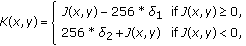 (3)
(3)where
 ,
,  , and
, and  is the function that returns the smallest integer larger than
  .
. -
(iii)
Obtain the binary image,
 , from image
  using Ostu's method [20] which calculates an automatic threshold (Figure 5(b)).
 -
(iv)
Compute the gradient image, G, using the Sobel horizontal (
 ) and vertical (
 ) edge operator followed by an image contrast enhancement [21] (Figure 5(c)).
 -
(v)
Compute the logarithm image [22], L, where the objective here is to enhance the iris pixels that form the central part of the eye (Figure 5(d)).
 using the following:
 and
and  are the mean and the standard deviation, respectively. These parameters are computed over the previously located eye rectangles.
 using
using
 ,
,  , and
, and  is the function that returns the smallest integer larger than
  .
. , from image
  using Ostu's method [
 ) and vertical (
 ) edge operator followed by an image contrast enhancement [
Eye location using and : (a) grayscale image, (b) binary image (B), (c) gradient image (G), and (d) logarithm image (L).
With the pixels that have been extracted from images B, G, and L, it is possible to obtain the previously mentioned random sample. This sample presents an ellipse shape where an elliptical model has been adjusted over this using the expectation maximization algorithm (EM) [23]. Special attention is paid to the center of the ellipse, because, it allows the exact position of the center of the eye center to be obtained. The ellipse axes determine the width and height of the eyes. The result is shown in Figure 6(b).

Expectation maximization algorithm over the spatial distribution of the eye pixels: (a) eye image, (b) ellipse parameters: center, axes, and inclination angle. (c), (d), (e), and (f) show other examples of this procedure.
The main reason behind using pixel information from a random sample is due to the fact that head movements, illumination changes, and so forth, do not allow complete eye pixel information to be obtained, that is, only partial information of the eye in images B, G, and L is available, where the elliptical shape prevails. This random information makes it feasible to use an algorithm that computes the parameters of a function which approximate the eye ellipse shape. EM computes the mean, variance, and the correlation of the  and
and  coordinates that belong to the eye. The initial parameters required to run the EM are obtained from a regression model adjusted using the least square method. The number of iterations of the EM algorithm is set to 10, and the sample size is taken to be at least 1/3 of the rectangles area
  . These parameters will be used in the eye state analysis presented below.
4.3. Tracking
There are a number of reasons for using a tracking module. The first is due to problems that were encountered using the VJ during this research. Another is related with the necessity to track the face and eyes continuously from frame to frame. A third reason is to reduce the search space thus satisfying the real-time condition requirement. The tracking process has been developed using the Condensation Algorithm (CA) in conjunction with Neural Networks (NNs) used for face tracking and with template matching for eye tracking.
4.3.1. The Condensation Algorithm
This contribution implements the CA that was proposed by Isard and Blake [24, 25] to track active contours using a stochastic approach. CA combines factored sampling (Monte-Carlo sampling method) with a dynamic model that is governed by the state equation

where  is the state at instant
  and
and  is a nonlinear equation and depends on the previous state plus a white noise. The goal here is to estimate the state vector
  with the help of system observation, which are the realization of the stochastic process
  governed by the measurement equation

where  is the measurement system at time
  and
and  is a nonlinear equation that links the present state plus a white noise. The processes
  and
and  are both white noise terms and are independent of each other. Also, these processes in general are non-Gaussian and multimodal. It must be pointed out that
  is an unobservable underlying stochastic process.
4.3.2. Neural Networks
Neural networks are used in a wide variety of pattern recognition and classification problems. Figure 7 shows several face examples used to train the backpropagation neural network used in this algorithm.

Examples of a face database which contain faces with different orientations: (a) left profile, (b) front view, (c) right profile, (d) down profile, and (e) up profile.
Before the neural network is trained, a two-part preprocessing step is necessary.
-
(i)
Contrast modification using gamma correction given by (6) with
 where this value has been determined experimentally [26]
 (6)
(6) -
(ii)
Remove the contour points by means of a masked AND operation shown in Figure 8(a).
 where this value has been determined experimentally [

Mask for face training and its result.
Next, the characteristic vector which consists of the pixel gray-level values from the face image is extracted. The rate of classification following training is greater than 93%.
4.3.3. Face Tracking
Previously, it has been mentioned that the VJ method presents problems when detecting faces that deviate from the nominal position and for different orientations; thus, to correct this disadvantage a face tracking method has been developed. To demonstrate this shortcoming, Figure 9 shows several different time instants where the VJ method is not capable of finding the driver's face. Figure 10 presents an extended example, where the true position and the VJ position are represented over a frame sequence. The true position has been retrieved manually.

The driver's face has not been found by the Viola Jones method during several time instants.

Example where the VJ method does not find the driver's face in a 100-frame sequence.
The main problem of the VJ method is that it is only able to locate the human face when it is positioned in front of the camera. This drawback leads to an unreliable system for driver analysis throughout the driving process which is highly dynamic, for example, when looking at the rearview or wing mirrors. Much effort has gone into correcting this problem resulting in an efficient tracker which has been implemented using CA combined with a backpropagation neural network.
Through recursive probabilistic filtering of the incoming image stream, the state vector

for a driver's face is estimated for each time step  . It is characterized by its position, velocity, and size. Let
  represent its center position,
  its velocity in both
  and
and  directions and
  the size in pixels. The measurement vector is given by

The dynamics of the driver's face has been modeled as a second-order autoregressive process AR , according to

where  is the transition matrix proposed in [25], and
  represents the system perturbation at time
  . The most difficult part of the CA is to evaluate the observation density function. In this contribution to compute the weight
  for
for  , at time
  , a neural network value in the range of
  has been used; this provides an approximation of the face and nonface in conjunction with the distance and with respect to the face to track. This is similar to the work performed by Satake and Shakunaga [27] who have used sparse template matching to compute the weight
  of the sample
  for
for  . In this contribution, the neural network value is used as an approximate value for the weights.
The density function of the initial state is  , where
  is computed using the VJ method, and
  is given in [4]. A particle representation at time t is shown in Figures 11(a) and 11(b) and Figure 12 depicts the tracking process in which the green circle is the true position and the red cross characterizes a particle or hypothesis, whereas Figure 13 shows the probability over time. This tracker is highly flexible as the neural network includes faces and nonfaces for different head orientations under various illumination conditions. Table 1 presents further results for several sequences of drivers faces. The sequences come from the driver database, which was created to perform these experiments. The true face position has been retrieved manually.

One time step of the Condensation algorithm (a) predicted region, (b) particles regions.

Trajectory of the real and estimated face-center in a 100-frame sequence using the proposed tracker.

Estimated value of the a posteriori density of the face-center in a 100-frame sequence using the proposed tracker; the face is detected in the fourth frame.
4.3.4. Eye Tracking
For this task, the state of the eye is characterized by its position and velocity over the image. Let  represent the eye pixel position at time
  and
and  be its velocity at time
  in the
  and
and  directions, respectively. The state vector at time
  can, therefore, be represented by

The transition model is given by (11) which is a first autoregressive model AR

The evaluation of the observation density function is developed by a template matching strategy [27] that was truncated to reduce false detections. CA is initialized when the eyes are detected with the method described in the previous section plus a white noise, that is, similar to the face tracking case. Figure 14 depicts the eye trajectory tracking and Figure 15 shows the compute value of the a posteriori density function of each eye, both on a sequence of 100 images. Table 2 shows the eye tracking results that have been obtained from several sequences of images during the experiments.

Trajectory of the real and estimated eyes center in a 100-frame sequence.

Estimated value of the a posteriori density of the eye center in a 100-frame for right and left eyes; the eyes are detected in the fourth frame.
4.4. Eye State Detection
To identify drowsiness using eye analysis it is necessary to know its state, that is, open or closed, through the time and to develop an analysis over time, that is, to measure the time that has passed for each state. Classification of the open and closed state is complex due to the changes in the shape of the eye, among other factors, the changing position and the face rotations and variations of twinkling and illumination. All of these problems make it difficult to reliably analyze the eye. To overcome these shortcomings a supervised classification method has been used, more specifically, a Support Vector Machine (SVM). Figure 16 presents the proposed scheme for eye state verification.

SVM scheme for eye state verification.
4.4.1. Support Vector Machine
SVM classification [28–30] is rooted in statistical learning theory and pattern classifiers; it uses a training set,  , where
  is the characteristic vector in
  represents the class, in this case 1 for open eyes and 2 for closed eyes, and
  is the number of elements of
  . From a training set, a hyperplane is built that permits classification between two different classes and minimizes the empirical risk function [30].
Mathematically, SVM consists in finding the best solution to the following optimization problem:

where  is an
is an  by the
  vector,
  is an upper bound,
  is an
is an  by
by  matrix with
  , and
, and  is the kernel function. By solving the above quadratic programming problem, the SVM tries to maximize the margin between the data points in the two classes and to minimize the training errors simultaneously. Figure 17 depicts input space mapping to a high-dimensional feature space through a nonlinear transformation and its maximization process.

SVM representation.
4.4.2. Eye Characteristic Extraction Using a Gabor Filter
The Gabor filter was used by Daugman for image analysis, changing the orientation, and scale [18] where these are multiscale and multiorientation kernels. They can be defined by the complex function

where  and
and  are the scale and orientation parameters and
  is the standard deviation of the Gaussian kernel which depends on the spatial frequency to be measured, that is,
  . The response of the Gabor filter to an image is obtained from a 2D convolution operation. Letting
  represent the image and
  denote the response of a Gabor filter with scale
  and orientation
  to an image at point
  on the image plane by
  is obtained using

Various combinations of scales and orientations are more robust for the classification between open and closed eyes. Three scales and four orientations have been used to generate Figure 18; these are  and
and  which were obtained experimentally over an image size 30 by 20.

Gabor filter for and .
Once the response of the Gabor filter is obtained, the eye characteristic vector is extracted using a subwindow procedure described by Chen and Kubo [31] and denoted by  . This vector is computed using (15) for each subwindow of size 5 by 6. Figure 19 shows the subwindow diagram


Subwindow images from the Gabor filter.
To perform this analysis a training set has been built which consists of both open and closed eyes. The images come from diverse sources, under different illumination conditions and are from different races. A further important aspect of this eye database is that it contains images of different eye colors, that is, blue, black, and green. Figure 20 shows several examples of this database.

Examples from the eye database for daylight illumination.
Previous to SVM training, it is crucial to preprocess each image where this procedure involves histogram equalization, filtering using a median filter, followed by the sharpen filter. The median filter is used to reduce image noise, and the sharpen filter enhances the borders.
The main objective of the SVM training is to obtain the best parameters and the best kernel that minimizes (5). After several SVM training experiments, it was decided to use the RBF kernel, that is,  is
is  , and
, and  , where these parameters achieve a high training classification rate of close to 93%.
Table 3 presents results using this method computed for several sequences of drivers. It demonstrates a high correct rate of classifications.
4.5. Drowsiness Index
The eye-blinking frequency is an indicator that allows the level of driver drowsiness (fatigue) to be measured. As in the works of Horng et al. [12] and Dong and Wu [3], if for five consecutive frames or during 0.25 seconds the eye is identified as being closed the system issues an alarm cue, PERCLOS [7], which is also implemented in this system.
Figure 21 presents an instantaneous result for this system on a driver's image whereas Figure 22 pictures the drowsiness evolution index graph for a driver's drowsiness sequence. Additionally, other examples are show in Figure 25.

Day system instantaneous result.

Drowsiness index graph for a 900-frame sequence of a drowsy driver: (a) Perclos, (b) Horng-Dong and Wu index.
4.6. Distraction
It is estimated that 20% of traffic accidents are caused by driver distraction [1]. To detect this characteristic the driver's face should be studied because the pose of the face contains information about one's attention, gaze, and level of fatigue [4]. To verify driver distraction the following procedure has been implemented.
4.6.1. Face Orientation
The driver's face orientation is estimated using the eye position, with

where  , and
, and  correspond to the left and right eye positions, respectively. Equation (17) provides the classification limits. Figure 23 depicts an example of the face orientation and in Figure 24 an extended example is shown for the driver's face orientation using information from the eyes for a sequence of images


Face orientation.

Head-orientation monitoring over time in a 100-frame sequence.

Different stages of the proposed algorithm during daytime conditions and for several time instants, driving conditions and different drivers.
4.6.2. Head Tilt
The method described above presents problems when a monocular camera is used, and so, to overcome this drawback, this contribution has implemented a head-tilt based on neural networks. Keeping in mind that the driver face database is composed of face examples for five different orientations, the face is passed to the neural network to determine its orientation, specifically for the up and down cases. If the system detects that the face position is not looking straight on, an alarm cue is issued to alert the driver of a danger situation.
5. Night System Design
In this part of the work, the night system will be described, where this is based on the algorithm scheme shown in Figure 1(b). Note that it is composed of both software and hardware platforms. The main difference between this and the previous system is in perception system.
5.1. Perception System
The perception system is used to acquire visual information of the driver's head during nocturnal driving. It consists of three parts: a vision system, a synchronization system, and an illumination system; see Figure 26.

Perception system schema.
The first part is composed of a miniature CCD camera where the IR filter has been removed. This camera generates a composite video signal (PAL, phase alternating line). The second part takes the signal from the camera and splits it up into odd and even fields using the LM1881N video sync separator. In the third and last part, the illumination system, based on near-infrared (NIR) light (700–900 nm), contains two sets of NIR light-emitting diode (LED) rings (inner and outer) which produce odd and even image fields where the pupil effect is highlighted [3, 4]. The inner led ring surrounds the camera, while the outer leds are placed over a ruler in a symmetric position around the camera. Figure 27(a) shows this system, and Figure 27(b) provides an example of an illuminated driver's face from the NIR illuminator.

Perception system using infrared illumination (a) vision system, (b) drivers image, and (c) odd (top) and even (bottom) image fields.
Each frame is deinterlaced in both odd and even fields which contain the dark and bright pupil images, separately. Hence, the height of the odd and even image fields is a medium of the original image; this procedure can be seen in Figure 27(c): the top photograph is the even image field, and the bottom is the odd image field. Even an odd image will be used later on for eye detection.
5.2. Eye Detection
The bright effect pupil is the main principle behind locating the position of the eye. To do this sense, three images have been generated from the initial driver image, these are the difference image ( ), the edge image (
 ), and the bright part of the fast radial symmetry transform (FRST) image [32] (
 ).
).
The first image is computed using the absolute value of the pixel difference between the even and odd image fields; see (18). In this image most of the background and external light illumination has been removed, and the pupils appear as the brightest part

The second and third images are obtained using the Sobel Operator and the bright part of the FRST [32] over the difference image, respectively; these may be seen in Figures 28(a), 28(b), and 28(c)

where  and
and  are given by (5).

Difference (a), edge (b), and FRST (c) and their binary images (d), (e) and (f), respectively.
Most researchers only make use of the difference image for pupil detection; however, in real driving conditions, this image deteriorates due to external illumination, vibrations, and so forth and is also very sensitive to lighting conditions. In such circumstances, it is necessary to incorporate more robust information to improve the detection step. Therefore, in this paper, the edge and FRST images have been implemented to obtain enhanced results considering the aforementioned drawbacks.
Once all the images used to detect the eyes have been specified, the next step is to compute a binary threshold for the difference, edge, and FRST images. In the first of these, the threshold is obtained from a systematic analysis of its histogram, where two groups are formed. In the second case, the histogram is modelled using a Gamma distribution function where the 90% cumulative interval provides the threshold. Finally, in the third image, the maximum histogram value produces the required threshold level. This yields three binary images consisting of binary blobs that may contain a pupil.
The pupils are detected by searching within the entire image for the location of two blobs that satisfy a particular size, shape, and distance constraints. To remove false blobs an unsupervised classifier has been implemented, in this case, the SMV classifier, which is based on statistical learning theory and pattern classifiers. It uses a training set,  , where
  is the characteristic vector in
  represents the class, in this case 1 for open eyes and 2 for noneyes, and
  is the number of elements of
  [28]. Before training the SVM, it is crucial to preprocess each image, where this procedure involves histogram equalization, filtering using the median filter, followed by the sharpen filter. The median filter is used to reduce noise in the image, and the sharpen filter is used to enhance the borders. After this procedure a Gabor filter [31] is computed on each image of the eye database. Some combinations of scales and orientations are more robust for the classification between eyes and noneyes. One scale and four orientations have been used in this research; these are
  and
and  which have been obtained experimentally from an image size of 30 by 20 (in pixels). To perform this task, a training set has been built which consists of open eyes and noneyes, where an example is shown in Figure 29. Once the response of the Gabor filter is obtained, the eye characteristic vector is extracted and denoted by
  .
.

Gabor filter response for and .
After several SVM training experiments, it was decided to use the RBF kernel, that is,  is
is  , and
, and  ; these parameters achieve a high training classification rate of about 93%.
This exhaustive search detects the pair of eyes; this is followed by an ellipse fitting which is applied to each pupil, and the center of the resulting ellipse is the position of the detected pupil. This process is presented in Figure 30(b). These will be used later to initialize the eye tracker.

(a) Human face model using the eye position, (b) face and eye detection.
5.3. Face Detection
Once the eyes have been located, the system continues with driver face detection. To perform this task, a human face model has been developed considering the pupil's position and face anthropometric properties [19]. Let  and
and  be the center position of the right and left eye, respectively, and
  their distance (in pixels); the area of the face is obtained from the following equations:

where  is the centre of the face, and
  and
and  are the axes of the face ellipse. Figure 30 depicts this model and its result.
5.4. Tracking
The tracking process has been developed using the Condensation algorithm for face and eye tracking.
5.4.1. Face Tracking
This system uses the neural networks [33] and models and parameters proposed previously for face tracking. Now that the elements for tracking have been identified, only the backpropagation neural network training is developed in this section. Before training, a preprocessing step that consists of using a Gabor filter [18] with one scale and two orientations has been implemented. After this, the characteristic vector which consists of gray-level values of pixels coming from the face image is extracted. The rate of classification subsequent to the training is more than 92%. Figure 31 shows several face examples, and Table 4 presents experimental results. In this table, the true position has been retrieved manually.

Examples of the face database and its Gabor filter response.
The density function of the initial state is  , where
  is computed using the previous face detection method, and
  is given in [4]. Figure 32 shows the a posterior density function of the face center tracking.

Estimated value of the a posteriori density of the face-center in a 350-frame sequence using the proposed tracker; the face is detected in the fourth frame.
5.4.2. Eye Tracking
For this task, the state of the eye is characterized by its position and velocity. These parameters are also described in the diurnal system. To evaluate the probability observation density, a triangular density function based on the value of the difference image has been used (Figure 33). This function takes into account the gray-level value for the intensity of the illumination system.

Triangular density function.
CA is initialized when the eyes are detected from the method described in the previous section plus a white noise. In Table 4 the eye tracking results are presented, which have been carried out in several sequences of images. Again, the true position has been retrieved manually. Additionally, Figure 34 shows the a posterior density function of both eyes.

Estimated value of the a posteriori density of the eye center in a 350-frame for right and left eyes, the eyes are detected in the fourth frame.
To evaluate the probability observation density, a triangular density function based on a value from the difference image has been used. CA is initialized when the eyes are detected using the method described in the previous section plus a white noise. Table 4 shows the eye tracking results which have been obtained from several image sequences.
5.5. Eye State Detection and Drowsiness Index
To identify drowsiness from an eye analysis, knowledge of the eye's state is required, that is, open or closed, in time and to develop an analysis over large periods of time, that is, to measure the time spent in each state. Classification of the open and closed state is complex due to changes in the shape of the eye, the changing position, and face rotations, as well as variations in twinkling and illumination, and so forth. All of these factors make it difficult to reliably analyze the eyes. However, when using the edge and FRST images, the eye state may be computed satisfactorily.
The PERCLOS [7] has been implemented in this system. Figure 35 presents an instantaneous result of this system obtained from a driver's image, and in Figure 36 the evolution of the drowsiness index graph for a sequence of driver drowsiness is presented.

System instantaneous result.

Drowsiness index graph in a 341-frame sequence of a drowsy driver.
5.6. Distraction
This method is similar to the previous case, once the face is continuously located in time; a neural network is used to determine its orientation and to verify the driver's level of distraction. If the system detects that the face position is not facing forward, an alarm cue is issued to alert the driver of a danger situation.
6. Conclusions
In this paper, a research project to develop a nonintrusive and autonomous driver drowsiness system based on Computer Vision and Artificial Intelligence has been presented. This system uses advanced technologies which analyze and monitor the state of the driver's eye in real-time and for real driving conditions; this is driving conditions for both daytime and nocturnal situations.
In the first case, based on the results presented in Tables 1, 2, and 3, the algorithm proposed for eye detection, face tracking, and eye tracking is shown to be robust and accurate for varying light, external illumination interference, vibrations, changing backgrounds, and facial orientations. In the second case, and as presented in the results of Table 4, the system is also observed to provide agreeable results.
To acquire the data required to develop and test the algorithms presented in this paper, several drivers have been recruited and were exposed to a wide variety of difficult situations commonly encountered on roadways, for both daytime and nocturnal conditions. This guarantees and confirms that the experiments presented here are proven to be robust and efficient for real traffic scenarios. The images were taken using two cameras within the IVVI (Intelligent Vehicle based on Visual Information) vehicle (Figure 27(a)): a pin-hole analog camera connected to a frame-grabber for the nocturnal illumination and a fire-wire camera for the diurnal use. Besides that, the hardware processes 4-5 frames per second using an Intel Pentium D, with 3.2 GHz, 2 GB. RAM memory and MS Windows XP.
IVVI is an experimental platform used to develop the driver assistance systems for real-life driving conditions. The most up to date version is a Nissan-Note car; see Figure 37(a). This vehicle is equipped with a processing system, which processes the information coming from the cameras. The processing system is composed of three personal computers (Figure 37(b)).

(a) IVVI vehicle, (b) processing system.
For future work, the objective will be to reduce the percentage error, that is, reduce the amount of false alarms; to achieve this, additional experiments will be developed, using additional drivers and incorporating new analysis modules, for example, facial expressions.
References
Brandt T, Stemmer R, Mertsching B, Rakotonirainy A: Affordable visual driver monitoring system for fatigue and monotony. Proceedings of the IEEE International Conference on Systems, Man and Cybernetics (SMC '04), October 2004 7: 6451-6456.
Tian Z, Qin H: Real-time driver's eye state detection. Proceedings of the IEEE International Conference on Vehicular Electronics and Safety, October 2005 285-289.
Dong W, Wu X: Driver fatigue detection based on the distance of eyelid. Proceedings of the IEEE International Workshop on VLSI Design and Video Technology (IWVDVT '05), May 2005, Suzhou-China 397-400.
Ji Q, Yang X: Real-time eye, gaze, and face pose tracking for monitoring driver vigilance. Real-Time Imaging 2002, 8(5):357-377. 10.1006/rtim.2002.0279
Bergasa LM, Nuevo J, Sotelo MA, Vázquez M: Real-time system for monitoring driver vigilance. Proceedings of the IEEE Intelligent Vehicles Symposium, June 2004 78-83.
Fletcher L, Petersson L, Zelinsky A: Driver assistance systems based on vision in and out of vehicles. Proceedings of the IEEE Symposium on Intelligent Vehicles, 2003 322-327.
NHTSA : Evaluation of techniques for ocular measurement as an index of fatigue and the basis for alertness management. DOT HS 808762 National Highway Traffic Safety Administration, Washington, DC, USA; 1998.
Hagenmeyer L: Development of a multimodal, universal human-machine-interface for hypovigilance-management-systems, Ph.D. thesis. University of Stuttgart, Stuttgart, Germany; 2007.
Longhurst G: Understanding Driver Visual Behaviour. Seeing Machine, Canberra, Australia;
Armingol JM, de la Escalera A, Hilario C, Collado JM, Carrasco JP, Flores MJ, Pastor JM, Rodríguez FJ: IVVI: intelligent vehicle based on visual information. Robotics and Autonomous Systems 2007, 55(12):904-916. 10.1016/j.robot.2007.09.004
D'Orazio T, Leo M, Distante A: Eye detection in faces images for a driver vigilante system. In Proceedings of the IEEE Intelligent Vehicles Symposium, June 2004, Parma, Italy. University of Parma; 14-17.
Horng W-B, Chen C-Y, Chang Y, Fan C-H: Driver fatigue detection based on eye tracking and dynamic template matching. Proceedings of the IEEE International Conference on Networking, Sensing and Control, March 2004 7-12.
Viola P, Jones M: Rapid object detection using a boosted cascade of simple features. Proceedings of the IEEE Computer Society Conference on Computer Vision and Pattern Recognition, December 2001 511-518.
Branzan A, Widsten B, Wang T, Lan J, Mah J: A computer vision-based system for real-time detection of sleep onset in fatigued drivers. Proceedings of the IEEE Intelligent Vehicles Symposium (IV '08), June 2008 25-30.
Ji Q, Zhu Z, Lan P: Real-time nonintrusive monitoring and prediction of driver fatigue. IEEE Transactions on Vehicular Technology 2004, 53(4):1052-1068. 10.1109/TVT.2004.830974
Brookshear JG: Theory of Computation: Formal Languages, Automata and Complexity. Addison Wesley Iberoamericana; 1993.
Grace R: Drowsy driver monitor and warning system. Proceedings of Driving Assessment International Driving Symposium on Human Factors in Driver Assessment, Training, and Vehicle Design, 2001
Daugman JG: Uncertainty relation for resolution in space, spatial frequency, and orientation optimized by two-dimensional visual cortical filters. Journal of the Optical Society of America 1985, 2(7):1160-1169. 10.1364/JOSAA.2.001160
Gejgus P, Sparka M: Face Tracking in Color Video Sequences. The Association for Computing Machinery; 2003.
Otsu N: A threshold selection method from gray-level histograms. IEEE Transactions on Systems, Man and Cybernetics 1979, 9: 62-66.
Jafar I, Ying H: A new method for image contrast enhancement based on automatic specification of local histograms. International Journal of Computer Science and Network Security 2007., 7(7):
Wu Y, Liu H, Zha H: A new method of detecting human eyelids based on deformable templates. Proceedings of the IEEE International Conference on Systems, Man and Cybernetics (SMC '04), October 2004 604-609.
McLachlan GJ: The EM Algorithm and Extensions. John Wiley & Sons, New York, NY, USA; 1997.
Isard M, Blake A: Condensation: conditional density propagation for visual tracking. International Journal of Computer Vision 1998, 29(1):5-28. 10.1023/A:1008078328650
Isard MA: Visual motion analysis by probabilistic propagation of conditional density, Ph.D. thesis. Oxford University, Oxford, UK; 1998.
Parker JR: Practical Computer Vision Using C. John Wiley & Sons, New York, NY, USA; 1994.
Satake J, Shakunaga T: Multiple target tracking by appearance-based condensation tracker using structure information. Proceedings of the 17th International Conference on Pattern Recognition (ICPR '04), August 2004 3: 294-297.
Cristianini N, Shawe-Taylor J: An Introduction to Support Vector Machines and Other Kernel-Based Learning Methods. Cambridge University Press, Cambridge, UK; 2000.
Chang C, Lin C: LIBSVM: a library for support vector machine. 2001, http://www.csie.ntu.edu.tw/~cjlin/libsvm
Guyon I, Gunn S, Nikravesh M, Zadeh LA: Feature Extraction: Foundations and Applications. Springer, Berlin, Germany; 2006.
Chen Y-W, Kubo K: A robust eye detection and tracking technique using gabor filters. Proceedings of the 3rd International Conference on Intelligent Information Hiding and Multimedia Signal Processing (IIHMSP '07), November 2007 1: 109-112.
Loy G, Zelinsky A: Fast radial symmetry for detecting points of interest. IEEE Transactions on Pattern Analysis and Machine Intelligence 2003, 25(8):959-973. 10.1109/TPAMI.2003.1217601
Looney CG: Pattern Recognition Using Neural Networks, Theory and Algorithms for Engineers and Scientists. Oxford University Press, Oxford, UK; 1997.
Acknowledgments
This paper was supported in part by the Spanish Government through the CICYT projects VISVIA (Grant TRA2007-67786-C02-02) and POCIMA (Grant TRA2007-67374-C02-01).
Author information
Authors and Affiliations
Corresponding author
Rights and permissions
Open Access This article is distributed under the terms of the Creative Commons Attribution 2.0 International License ( https://creativecommons.org/licenses/by/2.0 ), which permits unrestricted use, distribution, and reproduction in any medium, provided the original work is properly cited.
About this article
Cite this article
Flores, M., Armingol, J. & de la Escalera, A. Driver Drowsiness Warning System Using Visual Information for Both Diurnal and Nocturnal Illumination Conditions. EURASIP J. Adv. Signal Process. 2010, 438205 (2010). https://doi.org/10.1155/2010/438205
Received:
Accepted:
Published:
DOI: https://doi.org/10.1155/2010/438205